Bo Deadly
Well-known member
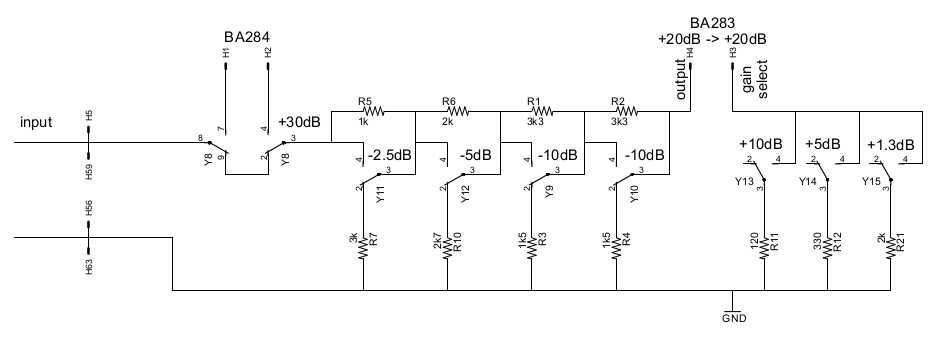
I want to build a Neve mic pre. I'm currently looking at the 1073 "fullpak" schematic. I'm just doing the mic pre and not the EQ. It looks like I want the first circuit of the BA284 board for +30dB of gain and another +30dB from the first circuit of the BA283 board and then +20dB from the output driver circuit.
But instead of the cumbersome 3 pole 22 position rotary switch, I am going to use the following relay stepped gain control circuit:
With 7 relays I can make all 20 5dB steps (plus the 2 off steps using a mute relay elsewhere). As you can see, it's based on two attenuators that can each do 0, -5dB, -10dB and -15dB with 2 relays (the extra poles switching in R15 and R24 adjust for error when both relays are engaged for an accurate -15dB).
However, I have some concerns. This is not really an equivalent circuit so I am concerned about any unforeseen differences. Specifically, the source impedance presented to each gain stage input does not exactly match the real 1073 circuit. But the real circuit values vary pretty significantly from ~1k-9k and in the case of the line input stage much lower (< 100 ohms) whereas my circuit will reuse the second stepped attenuator for both the mic and line steps that use attenuation (will be using both Carnhill VTB9045M mic and VTB9046M line input transformers). Is the impedance of the line input transformer much lower because it can handle a much lower load (load looks like ~1k near as I can tell)? Does anyone see a problem with these source impedance differences? For example, the source impedance of the lowest step (confusingly labelled "+10dB") the source impedance is < 33 ohms whereas in my circuit it would end up being ~2.5k. Anyone see a problem with that?
Also, an aside, the relay driver will be all set for 8 relayI want to build a Neve mic pre. I'm currently looking at the 1073 "fullpak" schematic. I'm just doing the mic pre and not the EQ. It looks like I want the first circuit of the BA284 board for +30dB of gain and another +30dB from the first circuit of the BA283 board and then +20dB from the output driver circuit.
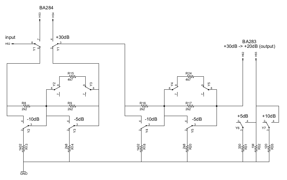
But instead of the cumbersome 4 pole 22 position rotary switch, I am going to use the following relay stepped gain control circuit:
With 7 relays I can make all 20 5dB steps (plus the 2 off steps using a mute relay elsewhere). As you can see, it's based on two attenuators that can each do 0, -5dB, -10dB and -15dB with 2 relays (the extra poles switching in R15 and R24 adjust for error when both relays are engaged for an accurate -15dB).
However, I have some concerns. This is not really an equivalent circuit so I am concerned about any unforseen differences. Specifcially, the source impedance presented to each gain stage input does not exactly match the real 1073 circuit. But the real circuit values vary pretty sigificantly from ~1k-9k and in the case of the line input stage much lower (< 100 ohms) whereas my circuit will reuse the second stepped attenuator for both the mic and line steps that use attenuation. Is the impedance of the line input transformer much lower because it can handle a much lower load (~1k near as I can tell)? Does anyone see a problem with these source impedance differences? For example, the source impedance of the lowest step (confusingly labelled "+10dB" in the Neve schematic) the source impedence is < 33 ohms whereas in my circuit it would end up being ~2.5k. Anyone see a problem with that?
Also, an aside, the relay driver will be all set for 8 relays but so far I've only used 7. So I have an extra relay. It would be nice if I could devise a 2.5dB step that works independently of any of the other steps so that I can effectively double the number of steps (40 2.5dB steps). Anyone have any ideas about how to add a + or - 2.5dB relay to this circuit? It needs to work independantly of any of the other steps of course.
Or perhaps you can suggest a better method entirely?
But instead of the cumbersome 3 pole 22 position rotary switch, I am going to use the following relay stepped gain control circuit:
With 7 relays I can make all 20 5dB steps (plus the 2 off steps using a mute relay elsewhere). As you can see, it's based on two attenuators that can each do 0, -5dB, -10dB and -15dB with 2 relays (the extra poles switching in R15 and R24 adjust for error when both relays are engaged for an accurate -15dB).
However, I have some concerns. This is not really an equivalent circuit so I am concerned about any unforeseen differences. Specifically, the source impedance presented to each gain stage input does not exactly match the real 1073 circuit. But the real circuit values vary pretty significantly from ~1k-9k and in the case of the line input stage much lower (< 100 ohms) whereas my circuit will reuse the second stepped attenuator for both the mic and line steps that use attenuation (will be using both Carnhill VTB9045M mic and VTB9046M line input transformers). Is the impedance of the line input transformer much lower because it can handle a much lower load (load looks like ~1k near as I can tell)? Does anyone see a problem with these source impedance differences? For example, the source impedance of the lowest step (confusingly labelled "+10dB") the source impedance is < 33 ohms whereas in my circuit it would end up being ~2.5k. Anyone see a problem with that?
Also, an aside, the relay driver will be all set for 8 relayI want to build a Neve mic pre. I'm currently looking at the 1073 "fullpak" schematic. I'm just doing the mic pre and not the EQ. It looks like I want the first circuit of the BA284 board for +30dB of gain and another +30dB from the first circuit of the BA283 board and then +20dB from the output driver circuit.
But instead of the cumbersome 4 pole 22 position rotary switch, I am going to use the following relay stepped gain control circuit:
With 7 relays I can make all 20 5dB steps (plus the 2 off steps using a mute relay elsewhere). As you can see, it's based on two attenuators that can each do 0, -5dB, -10dB and -15dB with 2 relays (the extra poles switching in R15 and R24 adjust for error when both relays are engaged for an accurate -15dB).
However, I have some concerns. This is not really an equivalent circuit so I am concerned about any unforseen differences. Specifcially, the source impedance presented to each gain stage input does not exactly match the real 1073 circuit. But the real circuit values vary pretty sigificantly from ~1k-9k and in the case of the line input stage much lower (< 100 ohms) whereas my circuit will reuse the second stepped attenuator for both the mic and line steps that use attenuation. Is the impedance of the line input transformer much lower because it can handle a much lower load (~1k near as I can tell)? Does anyone see a problem with these source impedance differences? For example, the source impedance of the lowest step (confusingly labelled "+10dB" in the Neve schematic) the source impedence is < 33 ohms whereas in my circuit it would end up being ~2.5k. Anyone see a problem with that?
Also, an aside, the relay driver will be all set for 8 relays but so far I've only used 7. So I have an extra relay. It would be nice if I could devise a 2.5dB step that works independently of any of the other steps so that I can effectively double the number of steps (40 2.5dB steps). Anyone have any ideas about how to add a + or - 2.5dB relay to this circuit? It needs to work independantly of any of the other steps of course.
Or perhaps you can suggest a better method entirely?