Neve 1290 Questions - Vintage Design

GroupDIY Audio Forum

Help Support GroupDIY Audio Forum:

This site may earn a commission from merchant affiliate links, including eBay, Amazon, and others.

maxwall

Well-known member
Joined
Nov 17, 2004
Messages
1,134
1290_3.jpg


The above 1290 is a Vintage Design board which I would like to take a shot at building. However I'm puzzled about some of the hookup's on this board layout. I need to clarify all the blue dot's starting with Letter 'A' to 'K'. I understand some are inputs , but from where ? Outputs - Where ?
gain to or from what ? etc. etc.

A ....input 1st voltage amp
B ....input 2nd Voltage amp
C ....output 1st Voltage amp
D ....output of 2nd Voltage amp
E ....Gain reduction pin - connects to wafer switch
F ....input for the output amp
G .... XLR input
H .....XLR input
I .... impedence switch - 300/1200 ohm
J ....XLR out pin 3
K ....XLR out pin 2


Also, I would like to add a rotary gain switch probably a 3 deck 1 pole per deck shorting 12-13 position rotary switch, where do the three or four wires of this switch solder to the board ?

wire 1- lowest switch point ex: -30db
wire 2- highest switch point ex: -70/80 db
wire 3 - all three poles of each deck get a separate wire then it is soldered to the board ? But where ? or what letter on the board ?


Also , the parts marked in yellow :

8 - 100uf caps 25Volts or 470 UF 6,3 -10 volts
Omron Relay's - what part # ? Are they all the same ?
 
If you go to Dan Alexanders site you can download adiagram which is the hook up information for the 1290. I used this to connect Tekay`s board up & after a few problems that were my testing setup I found that the board works really well. The details of how to wire up the rotary gain switch are also on this diagram.

The 100uF caps all want to be over 25v rating from memory.

The realays dont have to be the Omron brand, they just need the same foot print. You can use a relay with any energising voltage up to 24v Each relay has a resistor or wire link associated with it, & by changing its value you can compensate for the relay voltage.
 
Thanks, Rob

I'll have a look, you don't happen to have the link handy, do ya?
 
Rob,

Would this be the Neve 1290 document you spoke of.... ? Less the use of the inductor of course.


1290pinout.jpg
 
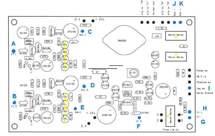
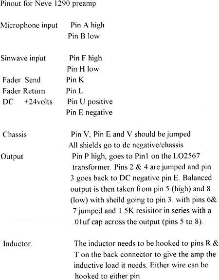
Anyone using that page of instructions for hooking up a 1290 should be aware of a couple of things:

The output description and accompanying inductor assumes you are using a non-gapped LO2567-type transformer (the api 2503/Profile 4804 works well in this application as well!) instead of the more typical-for-this-output-stage LO1166, which is gapped for the DC. If you are using an LO1166 or Sowter or Carnhill equivalent (gapped) the inductor is unnecessary. Simply attach the primary leads to pins R (+) and T (-).

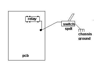
Secondly, this document suggests that Pin V and E be connected. I strongly suggest you not connect these directly, but instead, hook pin V (the module's chassis/earth) directly to the ground pin on the AC mains connector. Then, run separate wires from the AC ground pin to the chassis that your mounting the module in and another from the same AC ground pin to the +0v of the power supply. As for the module's pin E (labeled B- on Neve schematics), connect that ONLY to the +0v of the power supply.

When I originally racked my 1290's I used this instruction sheet, but experienced noise problems even at moderate gain settings. When I then changed the hookup to what I descibe above the noise went away.

If you are not working with an actual 1290 module, but instead TK's or anyone else's Neve-type PCB follow the same concept:

-Circuit board "ground" (Neve refers to this as "B-" on all their schematics) to power supply +0v
-Power supply +0v to AC connector ground pin (Neve refers to this as 'earth' which is pin V on almost all their old stuff)
-AC connector ground pin to chassis

Remember that these circuits, built as Neve intended, have the core of the transformers connected to chassis (earth). If you simply connect B- and earth signals together to one point on the chassis (as is typical of modern gear) then the current draw of the power supply (current, not voltage) is modulating through the chassis, and the transformer cores attached to the chassis. This creates noise in the audio signal.

By connecting the power supply +0v to the AC ground pin (NOT the chassis), then the shortest possible path from +0v to earth is straight down the AC cable. As long as this is the ONLY connection of B- to earth, the signal has nowhere else to go. If, however, you connect +0v to the chassis, and then attach the chassis to the AC ground pin, the current modulation of the power supply (again current, not voltage) modulates the chassis and, therefore, the transformer cores.

Yes, ultimately the two signals (B- and earth) are connected in either scenario, yet I can tell you from MUCH experimenting that one connection method (the more common one, unfortunately) creates noise while the other creates beautiful silence.

This is also true for the two-stage 1272-type circuits as well. I don't fully understand it all from a technical perspective, so I won't be able to defend my position theoretically.... just try it and you'll plainly see why Neve was so careful to connect their boxes this way.

Hope this helps all you Neve-types out there!

:thumb:

Much peace,

JC
 
Thats good info, So this seems to contradict star grounding method of modern circuits. I'll try this next time to compare.

In essence are you indicating that the power supply have a separate short path to ground (0V) while the chassis has a separate reference to ground (earth). What kind of noise is heard when the current is modulating thru the transformers - a hum ? or hiss ? or rumble ? curious to get some feedback on this ?

Hence two separate grounds : chassis and power supply - with the chassis acting as a floating ground ?

My last project in building a 1272 , I had a ground loop hum and eliminated it by making sure the chassis and all other grounds referenced to the grounding pin on the AC plug. The AC plug's ground was the hub of all other grounds connected - the center of the star ground. Even the metal panel mounted XLR ground pin and shell (tied together) referenced chassis ground which originated to the AC wall ground pin. I had the quietest circuit performance results from this configuration. Although I did not try separating chassis ground from power supply ground because I did not notice a very noisey circuit to warrant additional changes.
 
Hi Maxwall!
G & H is the main input from XLR, pin 2&3!
When I did this years ago I wanted all values exact as in the original, thats why I have parallelled caps on some places! As for the 4 x 100u, you can use a 470uF instead, 6,3 volt or higher.
 
I realized after posting the 1290 hookup table, it was for the original 1290 module , but I left it there for the sake of others to see or just a discussion piece.

A ....input 1st voltage amp
B ....input 2nd Voltage amp
C ....output of 1st Voltage amp
D ....output of 2nd Voltage amp
E ....Gain reduction pin - connects to wafer switch
F ....input for the output amp

1. in the above "A" , where does this input originate from ?
2. in the above "B", same question.
3. in the above "C", Where does the output originate from ?
4. in the above "D", same question
5. Gain reduction pin , probably one of the poles off the three deck rotary switch , which one ?
6. in the above "F" , where does the input for the output originate from ?
this is confusing.
 
The 1290 is built around two inputstages and one output stage!
First stage is only switched in when you need the extra 30dB gain from 55-80dB
Second stage is boosted in the 4 of the gain positions. This is controlled via the gainswitch and is connected to the "gain" pin.

45/75dB, +5dB boost
50/80dB, +10dB boost

If you download the 1290 schematics from www.technicalaudio.com

Maxwall markings / Neve 1290 schematics. EN10041
A = U, input stage 1
C = P, output stage1
B = D, input ´stage2
D = A, output stage2
E = C, gain boost stage2
F = L, input to output stage.

Hope this helps
 
Thankyou, Tekay

great explanation, that last posting is starting to make some real sense now.
 
I'm just full of questions (killing you'all) ........


Question on the various switches connected to the relays on the board.

Are the switches ground side switched ? ........ illustration below

1290_sw.jpg
 
Hi
After..........(same story) :cool:
Front.JPG

Top.JPG

Yes, I finished :grin: No smoke, everything works.
Only wait for new lower transformer to close box and fix VU on chassis.
If you saw front panel "T" mean Thomas, who help me very much (Thanks To My Brother In Preamps).
I add H.P.Filter, Hi-Z and VU.
I havent scope and I adjust voltage on 2N3055 collector to 21,4V. All voltages was like I find on others.
Sounds, nice. I put SM57, SM58, 441 than 414EB. First impression was "FAT SOUND" like through inaudable compressor.
With condenser I must turn gain to 30db. H.P. Filter works nice. Very loud :shock:
Three words: I am HAPPY :grin:
Also, I will make baffle beetween PSU and preamp because second channel have slightly higher hum.
One more time thanks to Thomas for transformer-gift and many answers (sometimes, maybe stupid :? ) and to others who help me.
Duka
 

Latest posts

Back
Top