chunger
Well-known member
Hello,
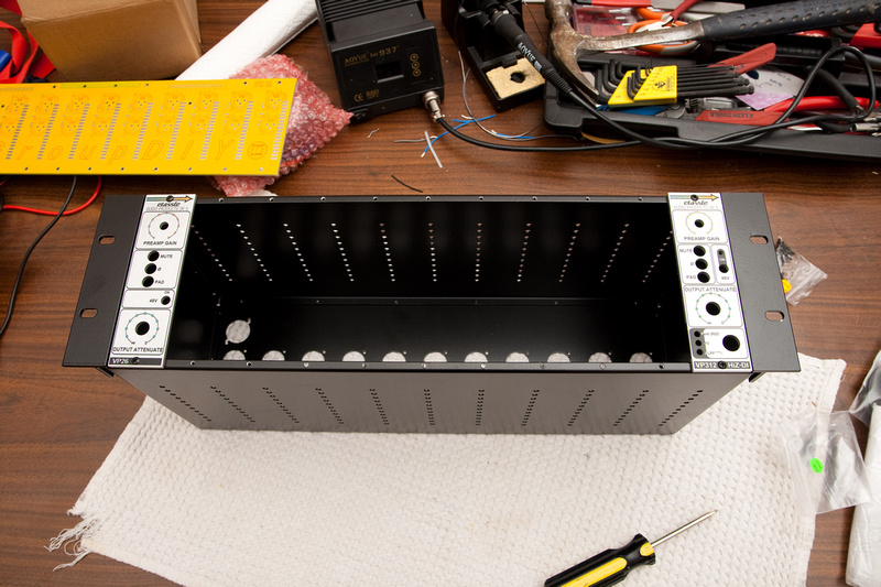
I'm pretty much a complete newbie to electronics. I've been lurking here in forums for some time trying to find answers and solutions to a lot of the questions I've been having. When I poked my head back into the forum a few weeks ago, I saw the GroupDIY 51X rack project in it's 2nd batch, and thought it might be time to jump in and see what happens. No point just sitting on the sidelines watching all the other kids have all the fun!
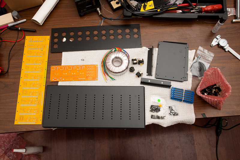
An email to Jeff at ClassicAPI.com (US liason for the project) revealed that a few folks had backed out for various reasons and a rack kit was available right now, so I jumped on it. I basically said, "Give me all the bits you have!"
Painting by numbers is probably a better 1st step for a beginner, and I think I'll probably have a lot of questions many of which are already answered in other threads, but I figure there are other people who are starting from the same point I am and a little more detailed information would not hurt the world. To a lot of folks, the stuff I take pictures of is probably so mundane that it's almost a waste of time, but for me, as a newbie, more information is preferred, and if I can make it easier for someone else to build this project, it'll be double success.
Another reason for my posting is so people who know better than me can warn me if I'm about to do something wrong and cause myself a lot of grief in the build process. . . also to warn of upcoming hurdles I should be aware of.
Every journey begins with a first step:
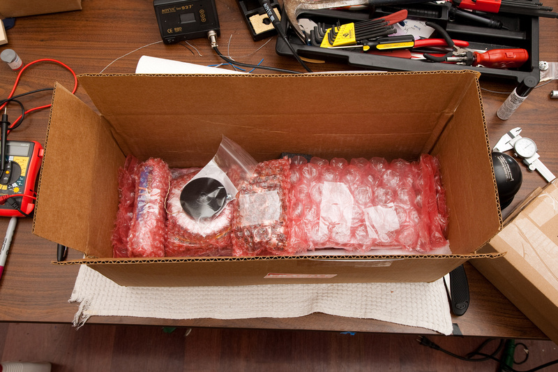
Shopping List (updated as needed throughout build)
Already purchased:
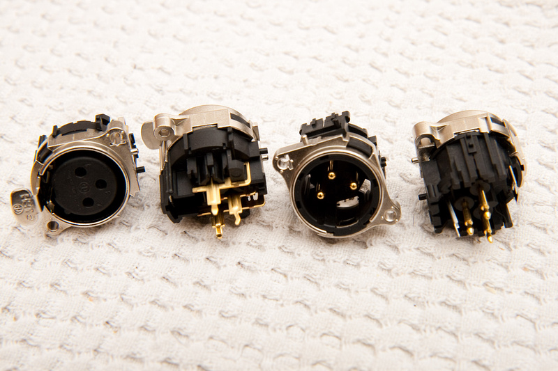
1x - Neutrik NC7FD-L-1-B -- 7 pin female panel mount D series XLR connector (Redco.com) $9.32
1x - Neutrik NC7FX-B -- 7 pin cable mount female XLR connector (Redco.com) $12.88
1x - Neutrik NC7MD-L-1-B -- 7 pin male panel mount D series XLR connector (Redco.com) $9.43
1x - Neutrik NC7MX-B -- 7 pin male cable mount XLR connector (Redco.com) $6.26
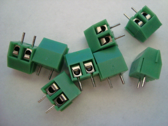
8x - 2 pole 3.96mm pitch PCB mount screw time block terminal -- (ebay) $1.00
3x 3M 929834-02-36 -- 36 pin 2.54mm pitch straight 1 row header (for rack XLR jumpers) (Mouser part number 517-834-02-36) $5.04
33x FCI 63429-202LF -- 2.54mm pitch shunt (gold plated) (Mouser part number 649-63429-202LF) $4.95
Purchased complete official PSU parts kit from Jeff Steiger at http://www.classicapi.com including PSU case, heat sinks, components, and hookup wire.
PSU parts kit from ptownkid http://www.diypartssupply.com $55 + $15 shipping
7 conductor cable from mptownkid $3.00 NOTE: provided cable was 24 AWG. I will not use this cable.
Replaced cable with Ancor Marine 541748 20AWG 8 conductor shielded signal cable purchased here http://www.westmarine.com/webapp/wcs/stores/servlet/ProductDisplay?productId=34969&catalogId=10001&langId=-1&storeId=11151&storeNum=10109&subdeptNum=10605&classNum=10610
Via http://www.apexjr.com/wire
16 AWG silver teflon hookup wire various colors for mains
Need to Order:
4x RAF 2100-440-AL-7 -- 440 thread 1/4" aluminum hex standoffs -- (Mouser 761-2100-440-AL-7)
5x Keystone Electronics 3049 -- #4 screw nylon shoulder washer (heatsink mounting) -- (Mouser part number 534-3049)
1x Kobiconn 161-R30148-E -- Power Entry Module -- (Mouser part number 161-R30148-E) $1.83
belden 5343FE 8 conductor shielded cable 18 AWG
(for PSU)
1x Vishay 2W01G-E4/51 -- BR1 -- Bridge rectifier -- (Mouser 625-2W01G-E4) $.58
4x Shindengen D5SB80-7000 -- BR11, BR21, BR31, BR41 -- Bridge rectifier -- (Mouser 627-D5SB80-7000) $4.20
1x Texas Instruments TL783CKCSE3 -- IC1 -- 700mah linear regulator -- (Mouser 595-TL783CKCSE3) $1.73
4x Fairchild Semiconductor LM350T -- IC11, IC21, IC31, IC41 -- 3A linear regulator adj. V -- (Mouser 512-LM350T) $3.32
5x Murata PV36W102C01B00 -- RV1, RV11, RV21, RV31, RV41 -- 1K trimmer resistor -- (Mouser 81-PV36W102C01B00) $4.42
20x AVX SR211C103KAR -- C1, C2, C3, C4, C11, C12, C13, C14, C21, C22, C23, C24, C31, C32, C33, C34, C41, C42, C43, C44
-- .01uf MLCC capacitor 100V 10% -- (Mouser 581-SR211C103KAR) $1.80
9x WIMA MKS2-.1/250/5 -- C9, C16, C19, C26, C29, C36, C39, C46, C49
-- .1uf poly film capacitor 250V 5% -- (Mouser 505-MKS2.1/250/5) $4.50
4x Nichicon UPJ1V101MPD -- C17, C27, C37, C47 -- 100uF 35V Aluminum Electrolytic Cap 20% -- (Mouser 647-UPJ1V101MPD) $1.68
4x Nichicon UFW1H102MHD -- C18, C28, C38, C48 -- 1000uF 50V Aluminum Electrolytic Cap 20% -- (Mouser 647-UFW1H102MHD) $3.28
2x Nichicon UFW2A102MHD -- C6, C8 -- 1000uF 100V Aluminum Electrolytic Cap 20% -- (Mouser 647-UFW2A102MHD) $3.36
4x Nichicon LKG1H103MESCBK -- C15, C25, C35, C45 -- 10000uF 50V Aluminum Electrolytic Cap 20% -- (Mouser 647-LKG1H103MESCBK) $33.20
I'm pretty much a complete newbie to electronics. I've been lurking here in forums for some time trying to find answers and solutions to a lot of the questions I've been having. When I poked my head back into the forum a few weeks ago, I saw the GroupDIY 51X rack project in it's 2nd batch, and thought it might be time to jump in and see what happens. No point just sitting on the sidelines watching all the other kids have all the fun!
An email to Jeff at ClassicAPI.com (US liason for the project) revealed that a few folks had backed out for various reasons and a rack kit was available right now, so I jumped on it. I basically said, "Give me all the bits you have!"
Painting by numbers is probably a better 1st step for a beginner, and I think I'll probably have a lot of questions many of which are already answered in other threads, but I figure there are other people who are starting from the same point I am and a little more detailed information would not hurt the world. To a lot of folks, the stuff I take pictures of is probably so mundane that it's almost a waste of time, but for me, as a newbie, more information is preferred, and if I can make it easier for someone else to build this project, it'll be double success.
Another reason for my posting is so people who know better than me can warn me if I'm about to do something wrong and cause myself a lot of grief in the build process. . . also to warn of upcoming hurdles I should be aware of.
Every journey begins with a first step:

Shopping List (updated as needed throughout build)
Already purchased:
1x - Neutrik NC7FD-L-1-B -- 7 pin female panel mount D series XLR connector (Redco.com) $9.32
1x - Neutrik NC7FX-B -- 7 pin cable mount female XLR connector (Redco.com) $12.88
1x - Neutrik NC7MD-L-1-B -- 7 pin male panel mount D series XLR connector (Redco.com) $9.43
1x - Neutrik NC7MX-B -- 7 pin male cable mount XLR connector (Redco.com) $6.26
8x - 2 pole 3.96mm pitch PCB mount screw time block terminal -- (ebay) $1.00
3x 3M 929834-02-36 -- 36 pin 2.54mm pitch straight 1 row header (for rack XLR jumpers) (Mouser part number 517-834-02-36) $5.04
33x FCI 63429-202LF -- 2.54mm pitch shunt (gold plated) (Mouser part number 649-63429-202LF) $4.95
Purchased complete official PSU parts kit from Jeff Steiger at http://www.classicapi.com including PSU case, heat sinks, components, and hookup wire.
Replaced cable with Ancor Marine 541748 20AWG 8 conductor shielded signal cable purchased here http://www.westmarine.com/webapp/wcs/stores/servlet/ProductDisplay?productId=34969&catalogId=10001&langId=-1&storeId=11151&storeNum=10109&subdeptNum=10605&classNum=10610
Via http://www.apexjr.com/wire
16 AWG silver teflon hookup wire various colors for mains
Need to Order:
5x Keystone Electronics 3049 -- #4 screw nylon shoulder washer (heatsink mounting) -- (Mouser part number 534-3049)
1x Kobiconn 161-R30148-E -- Power Entry Module -- (Mouser part number 161-R30148-E) $1.83
belden 5343FE 8 conductor shielded cable 18 AWG
(for PSU)
1x Vishay 2W01G-E4/51 -- BR1 -- Bridge rectifier -- (Mouser 625-2W01G-E4) $.58
4x Shindengen D5SB80-7000 -- BR11, BR21, BR31, BR41 -- Bridge rectifier -- (Mouser 627-D5SB80-7000) $4.20
1x Texas Instruments TL783CKCSE3 -- IC1 -- 700mah linear regulator -- (Mouser 595-TL783CKCSE3) $1.73
4x Fairchild Semiconductor LM350T -- IC11, IC21, IC31, IC41 -- 3A linear regulator adj. V -- (Mouser 512-LM350T) $3.32
5x Murata PV36W102C01B00 -- RV1, RV11, RV21, RV31, RV41 -- 1K trimmer resistor -- (Mouser 81-PV36W102C01B00) $4.42
20x AVX SR211C103KAR -- C1, C2, C3, C4, C11, C12, C13, C14, C21, C22, C23, C24, C31, C32, C33, C34, C41, C42, C43, C44
-- .01uf MLCC capacitor 100V 10% -- (Mouser 581-SR211C103KAR) $1.80
9x WIMA MKS2-.1/250/5 -- C9, C16, C19, C26, C29, C36, C39, C46, C49
-- .1uf poly film capacitor 250V 5% -- (Mouser 505-MKS2.1/250/5) $4.50
4x Nichicon UPJ1V101MPD -- C17, C27, C37, C47 -- 100uF 35V Aluminum Electrolytic Cap 20% -- (Mouser 647-UPJ1V101MPD) $1.68
4x Nichicon UFW1H102MHD -- C18, C28, C38, C48 -- 1000uF 50V Aluminum Electrolytic Cap 20% -- (Mouser 647-UFW1H102MHD) $3.28
2x Nichicon UFW2A102MHD -- C6, C8 -- 1000uF 100V Aluminum Electrolytic Cap 20% -- (Mouser 647-UFW2A102MHD) $3.36
4x Nichicon LKG1H103MESCBK -- C15, C25, C35, C45 -- 10000uF 50V Aluminum Electrolytic Cap 20% -- (Mouser 647-LKG1H103MESCBK) $33.20


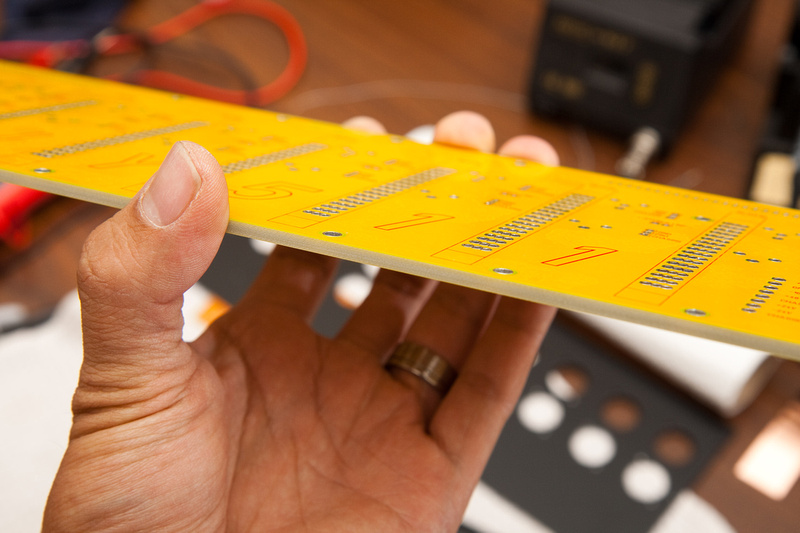
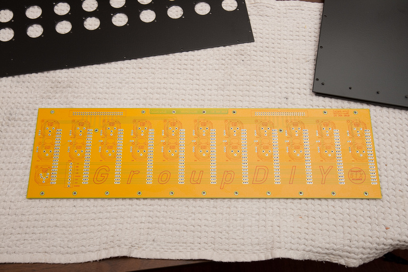
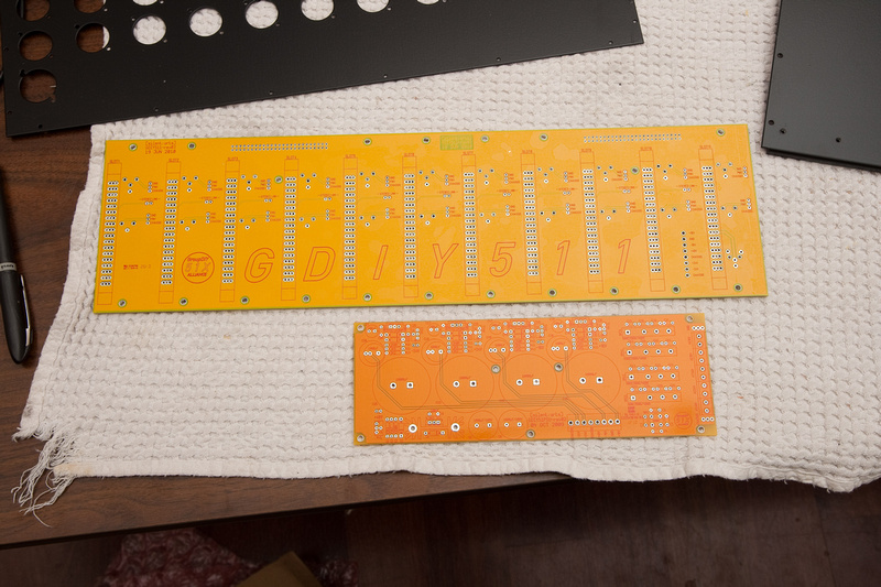
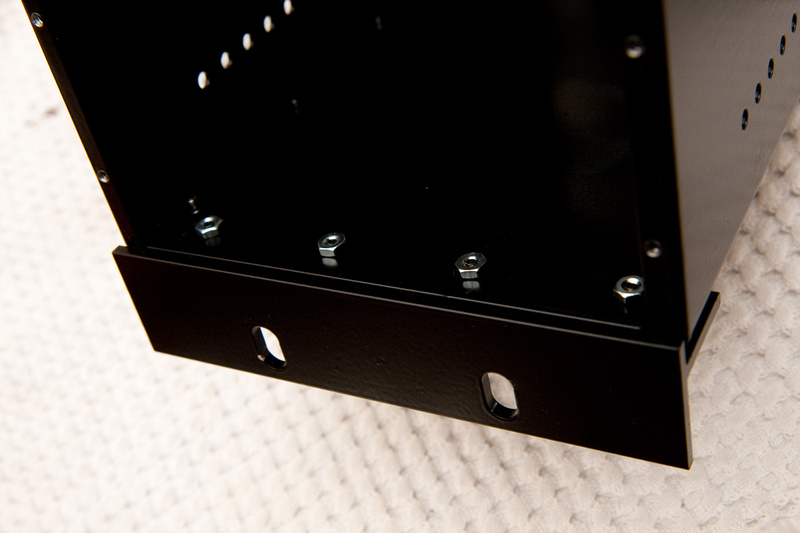
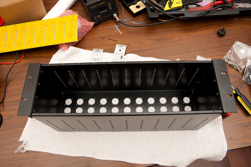


![Electronics Soldering Iron Kit, [Upgraded] Soldering Iron 110V 90W LCD Digital Portable Soldering Kit 180-480℃(356-896℉), Welding Tool with ON/OFF Switch, Auto-sleep, Thermostatic Design](https://m.media-amazon.com/images/I/41gRDnlyfJS._SL500_.jpg)


