Matador
Well-known member
JessJackson said:chunger said:I may be stating the obvious, but are all of the trimmer pot values verified and installed in the correct positions? Seems odd that the B+ would only have a few volts of adjustment range regardless of where the final voltage lands . . . and that the bias adjustment would be very touchy as that was quite a gradual change on my sample build per turn of the pot.
omg.. i'm a ******** for this but I thought all Adj pots were the same value.. simple mistake..
In Bias I have installed W502
In B+ I have installed W202
In Heater I have installed W104
Is there an easy way to remove these components because I'm having real difficulties desoldering the three legs at the same time.
Cheers
Thanks Chunger, I was going to suggest this check next.
I've had (limited) success removing these by turning the board upside down, then wiping the iron quickly across the three pins while applying sideways pressure on the pot body. You can do something similar with a chuck of solder wick or wire that has been tinned. If you can heat all three joints they should come out easily, then you can suck out the solder from the plated through holes with some fresh wick and some liquid flux or paste.
If you end up cutting them off, you can substitute in temporary resistors across the two outside holes using Ohm's law to your advantage. This should get you going until new trimmers arrive, as these voltages aren't particularly critical:
1) Heater - average loss is 0.2V (via I*R loss) by the time the voltage makes it to the tube pin. This means you want 6.5V at the supply side. Output heater voltage is set by the equation Vout = 1.25*(1+(R12+R10)/R9). Since R12 is 1K and R9 is 392, then the pot R12 should be set to 646 ohms. A 640 ohm resistor would be very close.
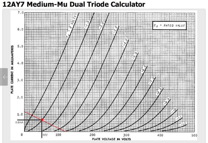
2) Bias - total return current is the plate current + the bleeder resistor R6. At 120V, R6 bleeds 0.25mA. The plate current at -1V bias at B+ 120V is 0.7mA, so we want 1V across R3 with 1mA, which means that R3 should be 1K ohms. 10% bias voltage up or down won't hurt things for testing.
R4 is more difficult, but you can get close by testing with your 180K resistor, trimming to 120V, then cutting out the pot and measuring the resistance between pins 2 and 3. Then substitute this with a fixed resistance.
Or, barring ALL of this, just get them out or buy new trimmers: they are only a few bucks for all of them.


![Soldering Iron Kit, 120W LED Digital Advanced Solder Iron Soldering Gun kit, 110V Welding Tools, Smart Temperature Control [356℉-932℉], Extra 5pcs Tips, Auto Sleep, Temp Calibration, Orange](https://m.media-amazon.com/images/I/51sFKu9SdeL._SL500_.jpg)


