Official C12 Clone - Build and Support Thread

GroupDIY Audio Forum

Help Support GroupDIY Audio Forum:

This site may earn a commission from merchant affiliate links, including eBay, Amazon, and others.
Can anyone say what's the largest output coupling cap that will fit in this kit (in place of the Erse)? I've ordered the kit, but want to experiment with some different caps.

If anyone can share the dimensions in inches or mm that would be so helpful to me.

Thanks,

Mike
 
Phrazemaster said:
Can anyone say what's the largest output coupling cap that will fit in this kit (in place of the Erse)? I've ordered the kit, but want to experiment with some different caps.

If anyone can share the dimensions in inches or mm that would be so helpful to me.

Thanks,

Mike

Somewhere in this thread Chunger posted a lit of caps he's tried:  I think in Erse it was up to 2uF.  There are several that are sold through JustRadios.com in the 1-2uF range (polypropylene) that fit: there are also Russian paper-in-oil types that work (not just for the coupling cap).  If you want to experiment, Mouser also sells some polyester film caps in the 160V range that should do the trick.
 
Thank-you Matador.

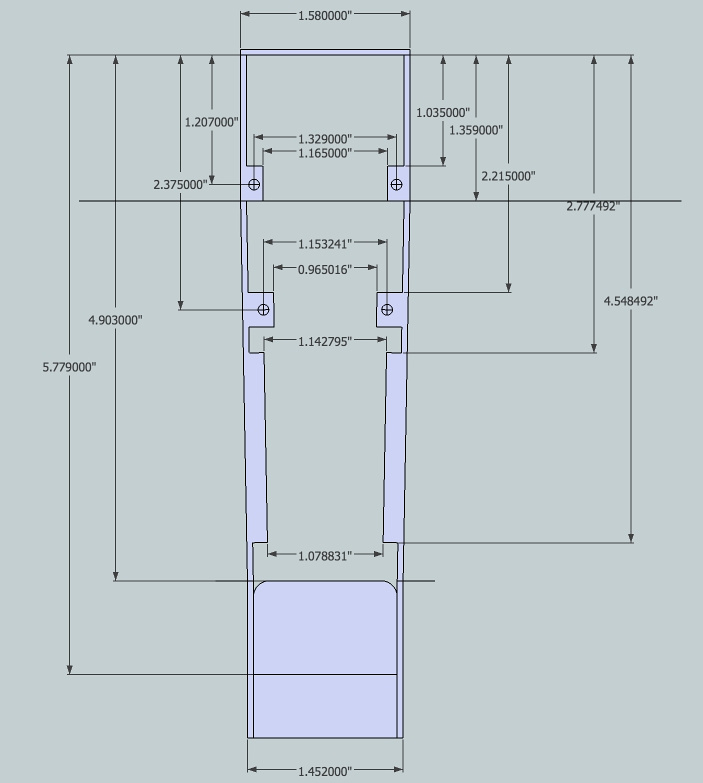
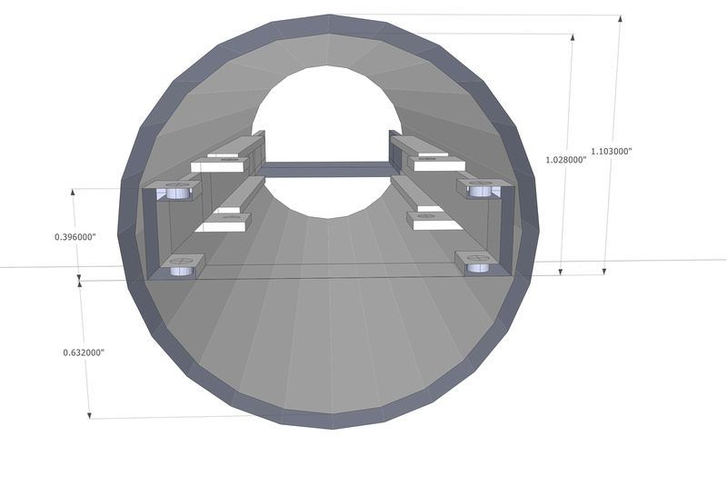
Any chance you might know the exact dimensions of the space between the two resistors on each side of the cap slot? it looks to me like about 0.7" is the largest possible diameter cap that might squeeze into there. But I'm guestimating using the build photos, extrapolating using Photoshop and triangulating using the moon phase and Sun motion arcs relative to the time the project began, using the Mayan calendar as a base of course...

Thanks much,

Mike
 
Does any body know what are the exact dimension of the pcb from studio939 matador/Chunger c12  pcb ?

Beeznees while make à body for the c12 diy but they need the dimension

Thanks
 
Just finished my c12 acril panel, sounds good in the first test...
DSC02357_www.kepfeltoltes.hu_.jpg

DSC02365_www.kepfeltoltes.hu_.jpg
 
I was wondering about using the terminal blocks, vs soldering the wires in the PSU directly to the board (pita!). So I googled what people thought of using terminal blocks, and found out something unrelated that really surprised me.

If using a terminal block, seems it is NOT OK to tin the wires first! Apparently over time, the solder does what they call a "cold flow" and can lead to the terminal block screw loosening and all kinds of badness. In fact, apparently this is even an electrical regulation of some kind, although I haven't googled enough to post it.

So, just an FYI for builders, and to Matador and Chunger, you might want to look into this, and if what I'm saying has merit, update the build instructions which do instruct to tin the wires first prior to inserting into the terminal blocks.

What apparently is ok, is to tin the very ends of the wires just to keep them from fraying, but that's as far as it goes.


From the last link:

"While wires may be crimped, they must never be tinned with solder prior to installation in a screw terminal, since the soft metal will cold flow, resulting in a loose connection and possible fire hazard."

Check me on this, I'm not trolling the thread! I've got your amazing kit coming (hopefully) soon in the mail, paid for, and was just browsing the build doc when I ran into this. If I'm wrong, cool beans. I just never wouldda guessed this would be an issue, and probably would have tinned the ends of the wires prior to insertion to the terminal blocks myself.

Best,

Mike

EDIT: Added links & Quote.
 
Phrazemaster said:
Can anyone say what's the largest output coupling cap that will fit in this kit (in place of the Erse)? I've ordered the kit, but want to experiment with some different caps.

If anyone can share the dimensions in inches or mm that would be so helpful to me.

Thanks,

Mike

Sorry for the late reply. . . these 2 pics may help determine the theoretical maximum diameter for the capacitor.

p1253499574-5.jpg


p1253499720-4.jpg


I have seen photos of people stuffing what appear to be larger than max caps into their builds because there is a bit of flex room inside the tube and frame rails when everything screws together.  Here are a list of caps that I personally have on hand and know fit but have not been able to experiment with yet because the Erse has worked quite well for me, and I have been experimenting with other variables that seem to effect the tone more dramatically.  I did try to find original type PIO caps, but to no avail.  Perhaps I am not looking in the right places.  But short of that, Matador's recommendation was to go with a good quality modern Polypropylene  or Polyester capacitor. . . which is what we have included in the kits.

Here are the caps that I have in my drawer (not yet tested in circuit) that I know physically  fit:

Sonicap .82uF Gen 2 600V
Sonicap 1uf Gen 1 200V
sonicap .68uf Gen 2 600V
Vcap 1uf OIMP 250V VQS-10EJ25
Mundorf Mcap ZN Audiophiler .68uf 250V (black)
Mundorf Mcap MKP 1uf 400V (white)
Mundorf Mcap MKP .56uf 630V (white)
Mundorf Mcap MKP 1.5uf 400V (white)
Solen MKP-FC 1uf 630V
Solen MKP-FC .56uf 630V

 
Chunger, you da man!

You consistently provide in-depth, thoughtful, caring and helpful details such as this.

Thanks much; helps tremendously!!

Best,

Mike
 
Wild idea: how about putting a switch in the mic to be able to activate the left or the right triode? Could make it so easy to utilize an entire tube once one side has been used up...

Whaddya think?

Mike
 
Phrazemaster said:
I was wondering about using the terminal blocks, vs soldering the wires in the PSU directly to the board (pita!). So I googled what people thought of using terminal blocks, and found out something unrelated that really surprised me.

If using a terminal block, seems it is NOT OK to tin the wires first! Apparently over time, the solder does what they call a "cold flow" and can lead to the terminal block screw loosening and all kinds of badness. In fact, apparently this is even an electrical regulation of some kind, although I haven't googled enough to post it.

So, just an FYI for builders, and to Matador and Chunger, you might want to look into this, and if what I'm saying has merit, update the build instructions which do instruct to tin the wires first prior to inserting into the terminal blocks.

What apparently is ok, is to tin the very ends of the wires just to keep them from fraying, but that's as far as it goes.


From the last link:

"While wires may be crimped, they must never be tinned with solder prior to installation in a screw terminal, since the soft metal will cold flow, resulting in a loose connection and possible fire hazard."

Check me on this, I'm not trolling the thread! I've got your amazing kit coming (hopefully) soon in the mail, paid for, and was just browsing the build doc when I ran into this. If I'm wrong, cool beans. I just never wouldda guessed this would be an issue, and probably would have tinned the ends of the wires prior to insertion to the terminal blocks myself.

Best,

Mike

EDIT: Added links & Quote.

Ferrules are recommended for terminating the ends of stranded wires when connecting to terminal blocks.

One source I found for ferrules and quality crimpers at a reasonable price is FerrulesDirect.com. (I'm in no way affiliated other than being a satisfied customer.) You can see the ferrules in one of my current projects (included my hex crimper fyi).
 

Attachments

  • 20150829_091023.jpg
    20150829_091023.jpg
    893.8 KB
I think everything about terminal blocks reported above is probably true:  but written from a perspective about using large(r) core wires capable of carrying 'significant' currents (e.g. mains or larger applications).

In this application, we are talking about tiny wires with relatively few strands.  Here's a list of remedies from least impactful to most:

1) Do nothing - it's probably fine
2) Open up the PSU and tighten the wires occasionally
3) Just don't tin the wires when assembling
4) After tinning, just bend a short 90 angle in the wire and assemble it with the hook pointing 'down'
5) Just don't tin the wires when assembling
6) Find tiny ferrules and crimp them during assembly
 
In light of this, I would recommend updating the build instructions to reflect it. Especially as it is a safety issue.

Don't tin the wires prior to insertion in to the terminal blocks. Simple.

I personally am going to solder the wires in place, as I do all my PSU's.

Best,

Mike

EDIT: I DID solder the wires in place! Was easy, and now it's a permanent professional PSU.

Only bummer is it's harder to check voltages as there aren't the convenient screw slots.
 
OK perhaps a stupid issue...

After installing the pattern switch, as per build pix, I noticed the flat part of the switch is on the top. Mounting the knob with the flat spot on the top with the screw against the flat spot,  results in the knob pointing down, not up, and doesn't line up with the silkscreen either.

I ended up turning the switch upside down, and it seems to match the silk screen.

And yes, I was very careful to follow the resistor numbering scheme as well as put the stop pin in the right place...

Unless you are suggesting to ignore the flat spot on the switch and mount the knob with the screw NOT against the flat spot?

I also measured the pattern output for the various pattern positions. With no microphone, I was getting something like 174V on the Figure of 8 pattern, about 85V on the Cardiod, and ~0V for the Omni pattern. Hoping this is correct.

Was able to setup the voltages per build instructions without problem using a 180K resistor strapped to ground.

Thanks for any thoughts.

Mike
 
A few of mine turned out the same way - I ended up eyeballing it and grinding a new flat on the other side of the pot shaft (the replacement Lorlin has a plastic shaft so this takes less than 2 seconds with a Dremel sanding wheel) so that the knob would line up (I didn't use the chicken knob, but rather an aluminum circular knob with a black dot indicator).

Those voltages look correct:  figure 8 should be the highest voltage, cardioid is roughly half the figure 8 voltage, and omni should be 0V.
 
I've got a Matador c12 v1.4 on my bench. While building it there are some details I'd like to double check. The Matador web store doesn't seem that eager to communicate. Is there any build guide for the v1.4 in this BIIIG thread or maybe at some other place on groupdiy?
I posted a similar message in this thread some days ago, but I can't find it now..? Oh, in addition to this, is there some site search engine on groupdiy.com that I should know about?

Cheers!

Edit: Eh, I found smart search, it was to plain, I guess...
 
Agreed it would be nice if it was more organized as to version changes..

I believe page 93 of this thread has some discussion about version 1.4, as well as a link on that page to another thread with a new build doc by Chunger.

In Chunger's and Matador's defense, it's tough to use a forum  like this to document and organize lots of revisions.

Maybe a meta thread listing per-version differences?

HTH
 
Phrazemaster said:
Agreed it would be nice if it was more organized as to version changes..

I believe page 93 of this thread has some discussion about version 1.4, as well as a link on that page to another thread with a new build doc by Chunger.

In Chunger's and Matador's defense, it's tough to use a forum  like this to document and organize lots of revisions.

Maybe a meta thread listing per-version differences?

HTH

Okay, so it's not me not being able to find the guide..? I couldn't find much info on the v1.4 board in the thread either, well it's mentioned on page 93. No mater if you chose to use a forum for build guide or not, I think it's a bit lame not to come up with an updated guide. Ah well, hopefully it's just yours and my lack of search skill. :)
 
Well....you have a point but consider:

All the info is there, if you read through everything, plus think about it (is is DIY after all, right)..the philosophy generally isn't to show you every tiny detail

Chunger's build guides are some of the best there are, anywhere--in fact he's raised the bar considerably compared to what we used to have.

It also takes a tremendous amount of time to organize the info.  This is probably the main factor.

Anyway I do head you, but the info is here and if you have a specific question I'm sure someone will jump in.

Best,

Mike
 

Latest posts

Back
Top