Official C12 Clone - Build and Support Thread

GroupDIY Audio Forum

Help Support GroupDIY Audio Forum:

This site may earn a commission from merchant affiliate links, including eBay, Amazon, and others.
Delta Sigma said:
He is, he's quite busy. Send him an email and get on his waiting list. I got a pair slightly faster than expected. His email address is on his website. Google Campbell Transmitter.

Any idea what his lead times are right now?  I've emailed him earlier this week, but haven't heard back yet.  I would expect 2 or 3 months, maybe longer. 

Brandon
 
Brandon, sorry I am so slow at responding. All my OEM manufacturers are bringing out new mics and so I've been swamped. Unfortunately I am still a 1 man operation and so I am also head cook and bottlewasher.
I try to get to everything :)
 
Tim Campbell said:
Brandon, sorry I am so slow at responding. All my OEM manufacturers are bringing out new mics and so I've been swamped. Unfortunately I am still a 1 man operation and so I am also head cook and bottlewasher.
I try to get to everything :)

Haha!  No worries, Tim.  I hope I didn't come across as upset.  I hadn't taken it personally.  :) I will now look forward to your reply!

Brandon
 
Tim Campbell said:
Brandon, sorry I am so slow at responding. All my OEM manufacturers are bringing out new mics and so I've been swamped. Unfortunately I am still a 1 man operation and so I am also head cook and bottlewasher.
I try to get to everything :)

just sent you an email about purchasing 2 maybe 3 capsules from you.

Can someone chim in on Tims buying process?
 
Hi everybody,

Just a thought. Has anyone tried different regulators for the heater? There are some discussions on some threads on the change of reg between LM317 vs LT1086 or other varieties, (for heater supply). On paper it should not make much of difference perhaps, but some people swear on real life listening tests, and I would like to ask the community on this? Also would it be possible to swap between these in the current PSU schematic?
Best regards
Mark
 
Delta Sigma said:
Measure your voltages on your Polar pattern pin. Should be pin 4 inside the PSU and pin 3 inside the mic. Measure in both places. Measure in Omni, cardioid and fig 8. and post the voltages here.
 
marked said:
Hi everybody,

Just a thought. Has anyone tried different regulators for the heater? There are some discussions on some threads on the change of reg between LM317 vs LT1086 or other varieties, (for heater supply). On paper it should not make much of difference perhaps, but some people swear on real life listening tests, and I would like to ask the community on this? Also would it be possible to swap between these in the current PSU schematic?
Best regards
Mark
They are equivalent in operation, although I'm not sure the pinout is exactly the same.

LM317 has slightly worse dropout, however has better specified ripple rejection with a bypassed adjustment pin (80dB versus 75dB).  Provided the two devices are trimmed so that the voltages are the same, I can't see why there would be any difference.

Most arguments between these regs have to do with powering audio circuit rails, and how the output impedance of the regulator may affect things if it changes within the audio band.  But a heater is essentially a 10-20 ohm, 3W resistor, not a high-gain preamp. ;)
 
Delta Sigma said:
Measure your voltages on your Polar pattern pin. Should be pin 4 inside the PSU and pin 3 inside the mic. Measure in both places. Measure in Omni, cardioid and fig 8. and post the voltages here.
I measured at the power supply so far. I am getting omni 5.2 MV cardioid 13.1MV and figure 8 197.1v
 
doggy6812 said:
I measured at the power supply so far. I am getting omni 5.2 MV cardioid 13.1MV and figure 8 197.1v
So that's 5.2 "milli-volts" (hopefully not Mega-volts)  ;) ?  Measured with nothing plugged in to the PSU, right at the 7-pin connector?

With nothing plugged in, can you measure all 7 pins and let us know?
 
I've finished my C12 a while ago but it really lacks some highs compared to some other microphones I have build (EF47, U67, U47,...), while I understand that it should be a rather bright microphone.
I've build it with the best parts I could find (Tim Campbell capsule, 5 star 6072 tube, AKG transformer) so I'm guessing it might be the caps.

I used an 0,4uF PIO k42y-2 for C12, and what I believe are 4000 pF polystyrene caps for C10 and C11. These caps have a marking that says RUWEL 4000/10 500v.
And parallel with these 2 caps, as well as for C13 I used 1000 pF polystyrene caps. These are marked 1n0 F250 V9KS.

Maybe some of these caps are wrong?
Anyone any idea what could be the problem?
 
What akg transformer? Could be the tube and the transformer don't get along. Maybe you get some HF roll off? Can you measure the frequency response of the circuit?
 
Well actually it's the T14 transformer build by Haufe, so it should work.
I've tried it with 2 different 6072 tubes but in both cases it lacks high end.

I can indeed try to measure the HF respons of the circuit. Where do I inject the soundwave to do so?
 
Hank Dussen said:
Well actually it's the T14 transformer build by Haufe, so it should work.
I've tried it with 2 different 6072 tubes but in both cases it lacks high end.

I can indeed try to measure the HF respons of the circuit. Where do I inject the soundwave to do so?

Can you post a recording of something so we can hear it? Also are you using a mic pre? What audio interface are you using? Have you checked the cables and there solder connections?
 
I've used different preamps (DIY API, SSL, etc...) and different interfaces and by it's own it wouldn't be that noticeable but compared to other mics (U47, U67,...) recorded together with the C12, the latter definitely lacks highs.
The solder connections look good and the cable reads fine.
I'll try to post some recordings later tomorrow.
 
Hank Dussen said:
Well actually it's the T14 transformer build by Haufe, so it should work.
I've tried it with 2 different 6072 tubes but in both cases it lacks high end.

I can indeed try to measure the HF respons of the circuit. Where do I inject the soundwave to do so?

Just inject the signal diffectly into tube grid connection. You don't have to disconnect the capsule.  You can use REW software, -30 to -20db level. It will give you insight into FR, THD, phase shift. Simple setup and quite revealing.
 
Hello all. I finished this C12 build and the mic works fine, but I ran into a couple differences with the documentation that I'm hoping someone can help me understand.

1. All the voltage readings match the documentation except: when the mic is attached, the bias voltage is 0.03. And no amount of changing of the bias trim pot makes a difference in the voltage. Could something be connected incorrectly? Without the mic attached the bias voltage is -1.03, just like the documentation.

2. My PCB is different than what's in the documentation. I wonder if this impacts the issue I'm having with the bias voltage.

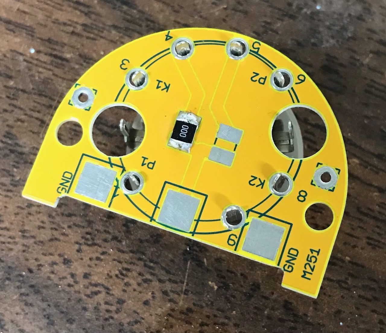
Here is what my PCB looks like:

mine.jpg


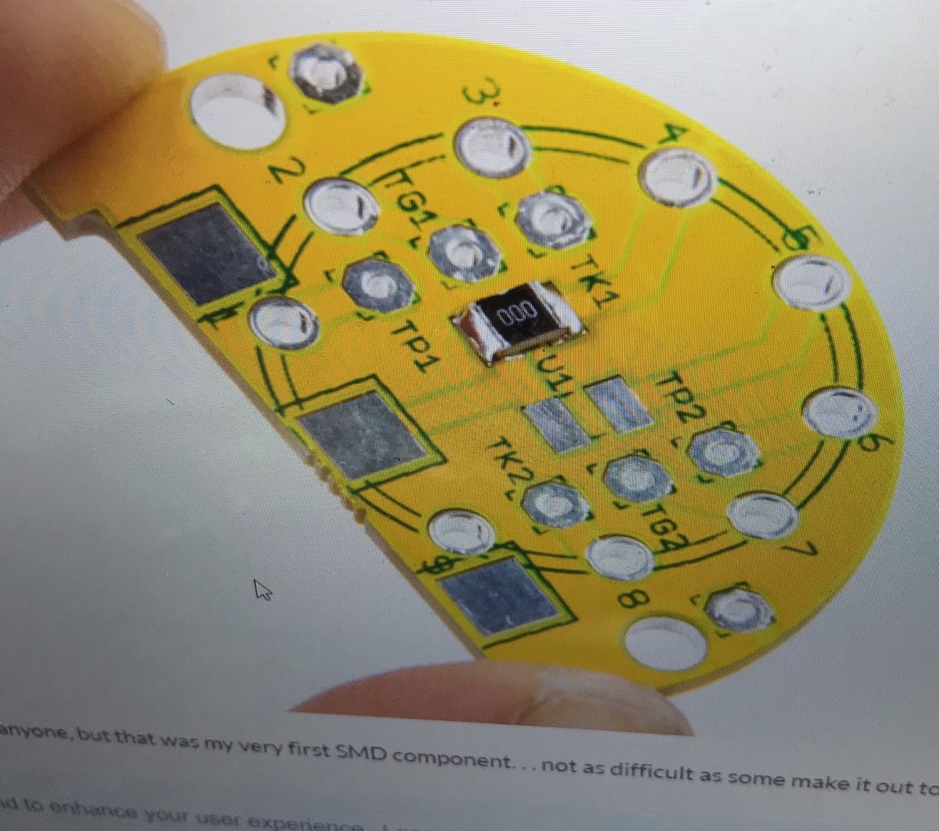
And here is what it looks like in the documentation:

documentation.jpg


There is nowhere to solder pins 2 or 7 on the PCB. Similarly, the documentation says to solder the grid wire to TG1, but TG1 doesn't exist. Tracing the schematic, I see that TG1 on the old PCB goes to pin 2 of the tube, so I soldered the grid wire to pin 2 of the tube (I'm using that side of the tube; P1 and K1).

The mic works fine, but I would really like to know if there is a problem with the bias voltage and if it can be fixed. Is there something else I can test with the meter to track down the issue?

Thanks in advance for your help. I am fairly green when it comes to electronics, so I'm grateful for any assistance that can be provided.

Cheers,
Chris
 
My intention with the original PCB was that one could fit the wires to the tube board, then attach the tube board and cut the wires to length.  However the latest design does away with separate solder points, because in reality it's just easier to solder directly to the socket connections that stick through, and it makes the tube board simpler.

So TK1 = K1, TP1 = P1, etc.  Pins 2 and 7 are the grids, so just solder directly to the socket leg that pokes through the hole.

Where are you measuring the bias voltage?  I'm guessing you are measuring it right at pin 2 of the tube socket?  You can't measure it there, because of the 280M worth of resistance.  Measure it at the P4 node directly as it enters the PCB down at the bottom edge near the transformer/XLR connector.
 

Latest posts

Back
Top