Matador
Well-known member
Interesting. That actually looks correct.
Let's debug the bias supply next: try the following in sequence:
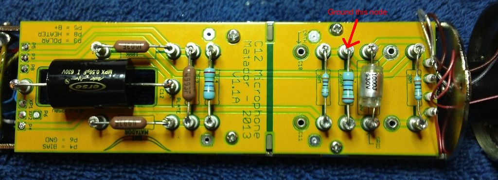
1) Instead of shorting the grid, short the turret where R11, R15, and C10 connect. This is the node at the turret right "above" the upside-down turret called "CATH". In your second picture, it is the next turret to the right along the top (you can see that the second, third, and fifth turrets have a link together).
You should observe similar behavior as directly shorting the grid.
2) Lift up C10 on the underside where it connects along the top (next to your purple wire), and remove the short from step 1 above. See what happens to B+ and plate voltage (pin 1).
Something is odd with one of the three components above (R11, R15, or C10).


