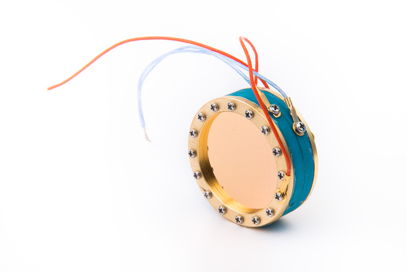
Official C12 Clone - Build and Support Thread

GroupDIY Audio Forum

Help Support GroupDIY Audio Forum:

This site may earn a commission from merchant affiliate links, including eBay, Amazon, and others.
Melodeath00 said:
Please do. For reference, my interface is a Focusrite Liquid Saffire 56, and the acoustic guitar was peaking at about -12dBFFS for the C12 at Preamp gain of 7. It's quite quiet IMHO.

Here's a link.

http://soundcloud.com/woot-8/sets/c12-test

First, I stole your chord progression and left some "silence" at the end. This is Matachung C12 w Beesneez new CK12, Auricap 0.56uF coupling cap and early 70's 6072 --> Drip "Ultra" 47 --> Apogee Symphony.

Second, is another little test to see how it sounds with some layers. Same recording chain. Some high pass filters, but otherwise no EQ/comp etc.

This is a quick cover of "Blind Sighted Faith" by The Dunwells. Apologies if the Vox are a little wobbly, I'm not a singer!

Cheers,

Matt
 
Sounding good woot! I was wondering about the Beez Neez Ck12  I have three of Tim's capsules which sound wonderful but I wanted to get one more so I'd have a pair of 12's and 251's until the supply stopped... Might have to go for the Beez neez Ck12  8) Or just wait a bit longer...must resist!
 
Update:  Our 6 micron 34mm edge terminated capsules just came in and are live on the webstore. . . well suited for budget conscious builds.

p749273344-4.jpg
 
chrispsound said:
Does anyone have the part number for the Lorlin switch used in place of the stock switch in the power supply?  Thanks

Lorlin part #CK1454.  Mouser part #10WA364.  It's 1 pole, 12 positions.

Coincidentally, one needs an odd number of positions to get one exactly half (or right in the middle), which is cardioid.  Chunger's build process matches the 9-positions of the stock switch, so three positions are not used on the Lorlin.

However you can use the additionally supplied 400K resistors, and make an 11 position switch so that there is still an exact center, and you get two more polar patters for about 60 cents in parts. ;)

Just food for thought.

Also, a center detent, 1M linear potentiometer works here as well, and makes the polar patterns essentially "infinitely" adjustable in-between omni, cardioid, and figure-8.
 
Matador said:
chrispsound said:
Does anyone have the part number for the Lorlin switch used in place of the stock switch in the power supply?  Thanks

Lorlin part #CK1454.  Mouser part #10WA364.  It's 1 pole, 12 positions.

Coincidentally, one needs an odd number of positions to get one exactly half (or right in the middle), which is cardioid.  Chunger's build process matches the 9-positions of the stock switch, so three positions are not used on the Lorlin.

However you can add two more 400K resistors, and make an 11 position switch so that there is still an exact center, and you get two more polar patters for about 60 cents in parts. ;)

Just food for thought.

Also, a center detent, 1M linear potentiometer works here as well, and makes the polar patterns essentially "infinitely" adjustable in-between omni, cardioid, and figure-8.

Our kits have always been.supplied with 10 switch resistors
 
chunger said:
Matador said:
chrispsound said:
Does anyone have the part number for the Lorlin switch used in place of the stock switch in the power supply?  Thanks

Lorlin part #CK1454.  Mouser part #10WA364.  It's 1 pole, 12 positions.

Coincidentally, one needs an odd number of positions to get one exactly half (or right in the middle), which is cardioid.  Chunger's build process matches the 9-positions of the stock switch, so three positions are not used on the Lorlin.

However you can add two more 400K resistors, and make an 11 position switch so that there is still an exact center, and you get two more polar patters for about 60 cents in parts. ;)

Just food for thought.

Also, a center detent, 1M linear potentiometer works here as well, and makes the polar patterns essentially "infinitely" adjustable in-between omni, cardioid, and figure-8.

Our kits have always been.supplied with 10 switch resistors

Aye that was horridly written...let me fix that. ;)

However you can use the additionally supplied 400K resistors, and make an 11 position switch so that there is still an exact center, and you get two more polar patters for about 60 cents in parts. ;)
 
Finally installed the CT12 capsules tonight and notice an odd phenomenon.  One mic seems to have more low end, but is darker.  In fig 8 mode the two capsule sides seem to match relatively closely.  The other has one side that is very bright without as much low end, while the back side in fig 8 mode is very dark with almost nothing up top.

Mic one and miuc two in cardiod don't match closely at all.  One has body and is slightly dark while the other is very bright but thin.  I swapped tubes to rule that out and tested from a single PSU to make sure all was well there.  In build they only differ in that one mic uses the second triode (the fuller sounding one).

Where to start?  I'm pretty sure it isn't the capsules because a-there is tremendous difference between front and back diaphragm on the one in questions and b-they are brand new CT12s and the variance is greater than I'd expect from even two China caps of the same type.

Could it be the styros?  They are the only part that I can think would look okay but maybe got overheated or something.

Could it be the transformer?  Both measured okay but a few posts back I showed that one had skewed lams on one side.  OPR mentioned Oliver A told him that would have no effect on performance.

Any ideas would be appreciated because I'm at a loss.  It couldn't possible be the capsules...  ?
 
Hi Guys,

just checked my C12 pattern select and seems to be wired correctly but i only seem to be able to get Cardioid and Figure 8, no Omni? any ideas why this would be?
I am getting 0v at omni and 60v at cardioid 120v at fig8?

regards

Spence.
 
chunger said:
Update:  Our 6 micron 34mm edge terminated capsules just came in and are live on the webstore. . . well suited for budget conscious builds.

p749273344-4.jpg

Hi Chung,
I was just about to order another RK12 capsule(cause I have only one, the other is a RK47 and I don't like it for this build).
Now, I saw your new capsule, wich is cheaper than the RK12($109) and I'm kind of undecided...
It will be a great help in make me decide myself if you could post an audio clip with the C12 and your new capsule... can you, please?!

Thanks!

ps: even greater it will be if you could use another C12 with CT12 or HK12 for reference... :)
 
Category 5,
I've PM'ed you about this.
If your pattern switching is working correctly then I'd assume there's something wrong with your polarization voltages or something has happened to these capsules and they should be sent back to me to look at.

If the capsules are working as they should, have you checked that the pattern switching is working correctly or that on the capsule with extreme differences between halves that you're not collapsing the rear membrane.

No matter what the cause I'd be happy to check the capsules if they're returned to me.

 
Category 5 said:
I remember there was a procedure to test the styrenes in circuit but for the life of me can't find it now.  Anyone help?

I would first check some voltages:

1) So you have 60V at the junction where R12/R13/R14 meet?
2) Do you get 0V, 60V, 120V at the node "P3" right as it enters the microphone?
3) Are the backplates bridged together, or tied together at the PCB?
4) Ensure the front of the capsule reads as a solid ground (e.g. low ohms when measuring between the front capsule lug and the mike body/ground point).

To test the styrenes, lift one end of C11, then retest.  Then lift one end of C10 and retest.  Make sure you test one at a time. Those are filters, so the mike will work fine when lifted (just a bit noisier).  If after lifting either of these caps the sound recovers then you probably have a leaking styrene, and it clobbers the polarization voltages.
 
I finished up my pair yesterday and tried them out today.  I only have the stock capsules right now - should have a new pair in about a month.
These mics sound astoundingly good considering all the factors.  I'm very eager to swap capsules.

Thanks for the great project.
 
I have some preliminary test results of the Point to Point build vs. the PCB based mics and the results are so far completely inconclusive.  I post now because there was some overlap with Category 5's findings on the CT12 capsule.  I will likely send a capsule back to Tim to have a closer look.

So, I did 2 rounds of testing on the PTP build.  The results are completely inconclusive at best, but we have some results folks can look at which is probably better than no results.  A quick summary is in our listening environment, this particular point to point microphone sounds better than the particular PCB microphone, but the reasons for the difference point to component variation as opposed to differences invoked by ptp vs. pcb construction of the circuit.

1st test. . . the point to point microphone to our ears sounded more open than the pcb build.  These are close mic recordings of acoustic guitar.  Because shifting the mic position even 3/4" influences the tone dramatically, we recorded separate takes with each microphone.

Point to Point clip
https://drive.google.com/file/d/0B5bvhqkG9T7fV0pucDN2dlgzQk0/edit?usp=sharing

PCB clip
https://drive.google.com/file/d/0B5bvhqkG9T7fQmxmaXowQmtsd1E/edit?usp=sharing

After the results from the first test, my chosen method of result confirmation in the 2nd test session was to completely teflon isolate the hiZ section of the PCB build . . . basically modify and isolate the "lesser" microphone in steps until it rivals our "good" microphone. . .this is done with the same methodology as the point to point build, so the isolation characteristics should be identical.  The results to our ears were indistinguishable between the PCB configuration and the same microphone modified with teflon isolated HiZ.  Note, these are the exact same components re-used. 

PCB with teflon isolated HiZ section
https://drive.google.com/file/d/0B5bvhqkG9T7fUTBmeUJZSTlvV2s/edit?usp=sharing

Mathematically, even though in theory, it is far outside of the range that would effect circuit performance, it can be argued that the HiZ section could effect tone, so I isolated that section for testing.  By the same token, by the numbers, there can be no tangible gains minutely possible by isolating the low Z sections of the PCB, so while I can go further and teflon isolate the entire PCB based microphone, it would likely be a waste of time.  So, my leaning based on no perceptible sonic gains from isolating the most likely culprits from stray capacitance and current leaks was to examine the core components (Tube, transformer, capsule).  In our first test day, we had 2 tubes and the tubes did exhibit some tonal differences, and these differences did follow the tube between the 2 test microphones, but the differences were small enough for us to consider them "flavor" differences.

This testing was done on a pre-production prototype of the PCB board microphone, so the FC and RC screen prints were reversed on the PCB, which led me to wire up the front and rear capsules in reverse when I completed the modifications.  Back to what Category5 observed, the "rear" side of this particular CT12 capsule sounded much more open and nuanced than the front side when listening in cardioid mode on the bench after making the modifications.  For our testing purposes, to maintain consistency, I wired the microphone using the same capsule side as the 1st test when preparing the microphone for the 2nd round of testing. . . but, in studio after confirming no sonic improvements from isolating the HiZ, I remembered that the back side of the capsule was "better" when I tested on the bench, so I took out a soldering iron in studio and switched our PCB mic to the rear side of the capsule.


PCB microphone with isolated HiZ back side of capsule
https://drive.google.com/file/d/0B5bvhqkG9T7fZFVOS1BueDNSQk0/edit?usp=sharing

The effects of that change were noticeable/tangible.  The PCB microphone "closed the gap" significantly in openness and articulation compared to our baseline point to point build.

So, my take-away from this very imperfect test.

1.  This particular point to point microphone is the "better" microphone of the 2 tested.
2.  Teflon isolating the HiZ portion of the circuit yields no perceptible sonic gains.
3.  Switching to the back side of the capsule (essentially changing capsules) DID result in sonic gains.

Further testing is necessary to make a more solid determination, but my leaning at this point is the PCB setup is sound.  If isolating the HiZ section of the microphone produced tangible improvements, I would absolutely change the build documentation to reflect this as the "prescribed" build methodology.  We are committed to providing a kit that delivers uncompromising sonics!

More information can be derived from switching the capsules and transformers between the PTP microphone and the PCB microphone to see if that reverses the standing of the 2 builds.  Due to the now scarce nature of the CT12 capsules, the microscopically small mounting screws, and limited light and tools in the studio, I opt to make these preparations on my workbench for further testing instead of attempting the swap in-studio.

Note: the standard C12 PCB set can be easily modded to make partial or fully teflon isolated point to point builds by enlarging the turret holes with a 9/64 inch bit and buying a handful of Keystone 11308 press-fit teflon turrets.  The same 9/64 inch bit can be used to enlarge the grid connection point on the tube sub-PCB to float that connection as well.
 
Matador said:
Category 5 said:
I remember there was a procedure to test the styrenes in circuit but for the life of me can't find it now.  Anyone help?

I would first check some voltages:

1) So you have 60V at the junction where R12/R13/R14 meet?
2) Do you get 0V, 60V, 120V at the node "P3" right as it enters the microphone?
3) Are the backplates bridged together, or tied together at the PCB?
4) Ensure the front of the capsule reads as a solid ground (e.g. low ohms when measuring between the front capsule lug and the mike body/ground point).

To test the styrenes, lift one end of C11, then retest.  Then lift one end of C10 and retest.  Make sure you test one at a time. Those are filters, so the mike will work fine when lifted (just a bit noisier).  If after lifting either of these caps the sound recovers then you probably have a leaking styrene, and it clobbers the polarization voltages.

For now I am not sure which mic is correct or incorrect so they will be Mic 1 and Mic 2. 

Mic 1 is the one with the pronounced low end and the two diaphragms matching much closer in Fig 8 mode.

Mic 2 is the one with the high frequency lift, less low end, slightly less output and dark/muddy rear diaphragm in fig 8 mode.

The power supply belongs to Mic 2, and voltages were adjusted for Mic 2 but these measurements were both done with this PSU.

So my measurements as suggested above are

1 - Mic 1 - 58.3v  Mic 2 - 59.1v

2 - Mic 1 - 0v/50v/107.7v    Mic 2 - 0v/50.8v/108.4v  (measured at the PSU switch connections 0v/55.6v/120v)

3 - backplates are tied together at the PCB, but regardless of where you measure resistance is 0 (accepting the meter margin of error)

4 - Capsule front reads solid ground.

In no position do any of the diaphragms appear to contact the backplate.  All connections between capsule and pins read 0 ohms, as do the backplates measured at the tabs.

I may just send these capsules back to Tim to have him match them to the best of his abilities since i didn;t specify I needed them matched when ordering.

I must say it's very cool of Tim to respond here and take initiative to help out, as well as Mat & Chunger as always.  Much appreciated guys!

Didn't have time to lift the styrenes tonight but I have replacements on the way anyway.  Hoping it's them at fault.

If everything seems normal above I'll swap the capsules tomorrow and see if the problem moves with them.
 
Ha! I got a kick out of "microscopically small screws." I could have really used some type of magnetized screwdriver during the build, but maybe that wouldn't be recommended.

Thanks you for posting the test. I'm very happy with my C12, but now I'm curious to test the rear side of the capsule. Would putting the mic in Figure 8 and close miking something be sufficient to try to glean a difference between back and front? Or do I need to rewire the back to be the front and test in cardioid?
 
Just to add a little info.
I don't claim that both halves of every capsule or that every capsule I make are indistinguishable with each other.
This capsule is complex and made in small batches and so halves are matched within reason and capsules are matched more closely when asked. AKG's CK12 capsules are notorious for sounding similar in only a general way and vary wildly from one to another. Much of my methodology is aimed at mimicing these older capsules. Sometimes striving for more nuance and detail can result in variation.
Klaus Heyne talks repeatedly about the fact that he listens to both sides of every Neumann and AKG capsule he installs and finds differences every time and so selects the better half to use as the front facing membrane.
Monitoring over headphones while listening to fig 8 will very often result in difference in timbre because of phase differences between the 2 membranes and the headphones.
Factory made capsules can result in more consistent sound because they're made by the thousands resulting more halves for selection and methodology that results in more consistent results but less nuance and detail.
All that said, I try to keep differences to a minimum and am glad to address these variations where they are problematic.
As far as the screw size I use blame AKG. I'm only following their construction (M1's).
 
Hey Chunger thanks for sharing your samples. The only thing I would suggest, If I may, Is that you record your comparisons samples simultaneously from a distance of at least half a meter or more with the two mic capsules as close together as possible, This way proximity and slight positional differences matter less and it's easier to determine what is actually different about the mics without the distraction of positional and performance inconsistencies . Alternately record repeatable source one at a time from the same position ie. the playback from your studio monitors. It may also be better to use your new Chinese capsules for the test as they are probably more consistent as Tim pointed has out.
 
Tim Campbell said:
Just to add a little info.
I don't claim that both halves of every capsule or that every capsule I make are indistinguishable with each other.
This capsule is complex and made in small batches and so halves are matched within reason and capsules are matched more closely when asked. AKG's CK12 capsules are notorious for sounding similar in only a general way and vary wildly from one to another. Much of my methodology is aimed at mimicing these older capsules. Sometimes striving for more nuance and detail can result in variation.
Klaus Heyne talks repeatedly about the fact that he listens to both sides of every Neumann and AKG capsule he installs and finds differences every time and so selects the better half to use as the front facing membrane.
Monitoring over headphones while listening to fig 8 will very often result in difference in timbre because of phase differences between the 2 membranes and the headphones.
Factory made capsules can result in more consistent sound because they're made by the thousands resulting more halves for selection and methodology that results in more consistent results but less nuance and detail.
All that said, I try to keep differences to a minimum and am glad to address these variations where they are problematic.
As far as the screw size I use blame AKG. I'm only following their construction (M1's).
Thanks for chiming in, Tim! For the record, I do in fact blame AKG. Just having a little fun. I'm a happy customer! And my audio buddies have been blown away by this mic
 
Back
Top