Official C12 Clone - Build and Support Thread

GroupDIY Audio Forum

Help Support GroupDIY Audio Forum:

This site may earn a commission from merchant affiliate links, including eBay, Amazon, and others.
Hi!

Are there any build photos floating around regarding the capsule connections for the 251-style build, keeping intact the remote polarization? 

I have the C12->251schematic Matador posted but would love to see photos of the physical connections between the capsules and the board for extra clarity!

From the schematic, I think the connections are:

(1) FC -> FB on the circuit board, with a jumper to replace C13
(2) R15 tied to ground (or to tube bias set to 0V?)
(3) R11 and C10 are also removed
(4) FB& RB (tied together at capsule) ->RB on the circuit board
(5) RC ->RC on the circuit board

Correct?

Thanks so much,

Damon
 
Hi Chunger,

finished my two psu successfully. Got the Teflon Turrets today and would like to proceed with building.

Would you replace all turrets or only turrets forC12, C13, C11,  R14 ?
Which are the most critical points for sonical "improvements".

Quote: Note: the standard C12 PCB set can be easily modded to make partial or fully teflon isolated point to point builds by enlarging the turret holes with a 9/64 inch bit and buying a handful of Keystone 11308 press-fit teflon turrets.  The same 9/64 inch bit can be used to enlarge the grid connection point on the tube sub-PCB to float that connection as well.


Thank you for Support


Erich T.
 
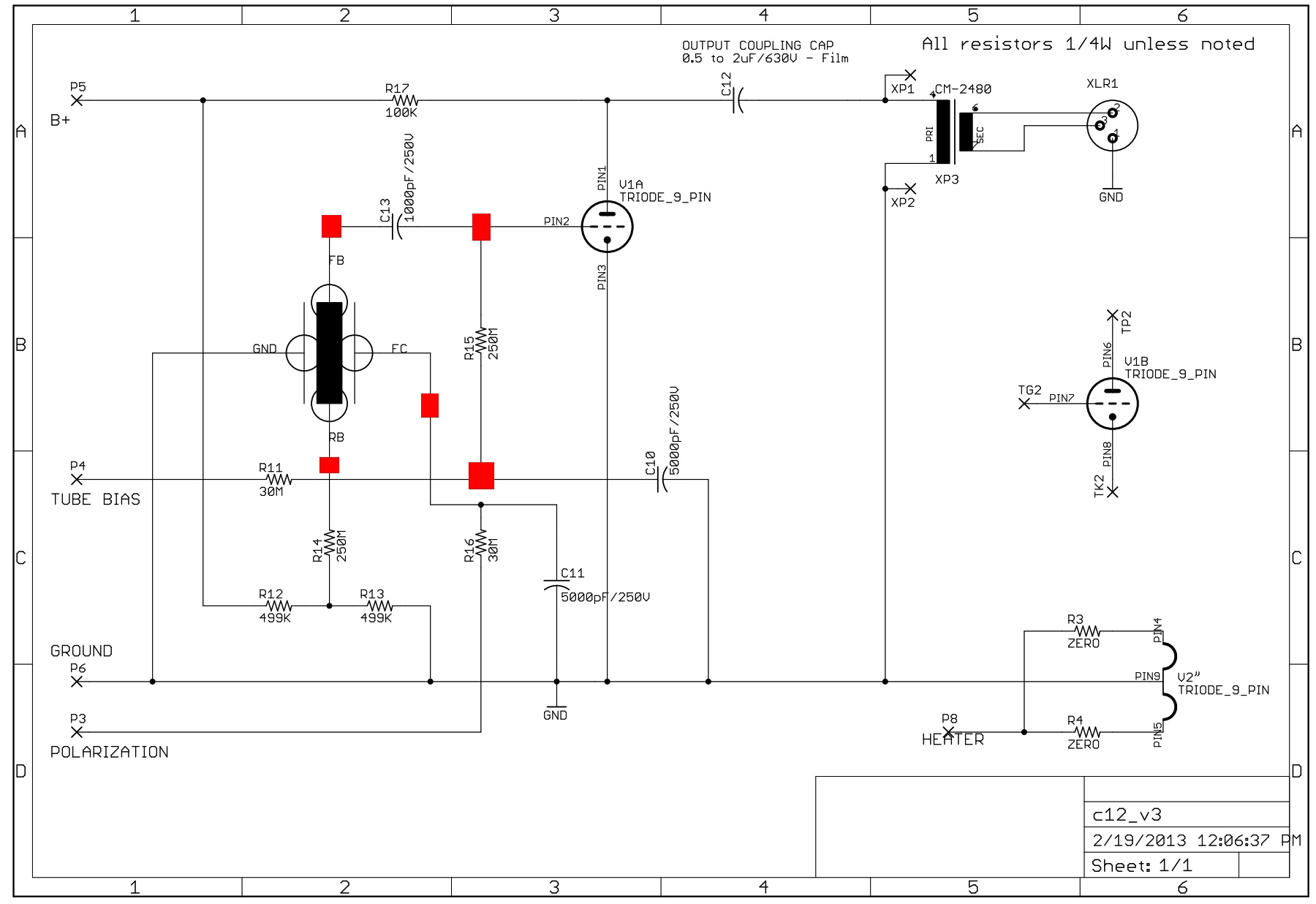
HI-Z nets marked in red.  Isolating anything else would be a waste.

hiz.jpg
 
Boy, this is frustrating. Removed all the big caps, verified proper values on my meter and reinstalled checking (again) they are in the right places by the bom and chungers photos. Exact same situation as before, no bias reading, B+ voltage drops quickly from about 20v down to about 6v. There's gotta be something else I can check.

Oh yeah and, Happy New Year all!
 
teacat said:
Boy, this is frustrating. Removed all the big caps, verified proper values on my meter and reinstalled checking (again) they are in the right places by the bom and chungers photos. Exact same situation as before, no bias reading, B+ voltage drops quickly from about 20v down to about 6v. There's gotta be something else I can check.

Oh yeah and, Happy New Year all!

Make sure youve got the transformer wired correctly.  Make sure the leads are making good contact and measure the voltage there.  Then measure the voltage at the output of the diode bridge.  Keep on down the chain until you can isolate the issue.

I had issues with one of my power supplies and damn near rebuilt the thing looking for the problem.  It turned out to be a 175v transformer instead of a 200v one.  they just substituted the part at the factory.  Had I tested from that point down the chain I'd have spotted the issue right away.
 
Bump.  If anyone can confirm these connections, I would be most appreciative!

ValveTone said:
Hi!

Are there any build photos floating around regarding the capsule connections for the 251-style build, keeping intact the remote polarization? 

I have the C12->251schematic Matador posted but would love to see photos of the physical connections between the capsules and the board for extra clarity!

From the schematic, I think the connections are:

(1) FC -> FB on the circuit board, with a jumper to replace C13
(2) R15 tied to ground (or to tube bias set to 0V?)
(3) R11 and C10 are also removed
(4) FB& RB (tied together at capsule) ->RB on the circuit board
(5) RC ->RC on the circuit board

Correct?

Thanks so much,

Damon
 
Make sure youve got the transformer wired correctly.  Make sure the leads are making good contact and measure the voltage there.  Then measure the voltage at the output of the diode bridge.  Keep on down the chain until you can isolate the issue.

I had issues with one of my power supplies and damn near rebuilt the thing looking for the problem.  It turned out to be a 175v transformer instead of a 200v one.  they just substituted the part at the factory.  Had I tested from that point down the chain I'd have spotted the issue right away.
Thanks for the suggestions, any and all are hugely appreciated.
Transformer 175v wires going to 200v terminal, nice and snug. I'm not entirely sure what the voltages should be at different points in the circuit, but measuring from ground to the diodes I'm getting D2- 116v/247v, D1- 116v/-.7v, D4- 116v/247v, D3-116/-.7v

Resistors:
R1- 245/11.1
R2- 11.1/5.8
R5- -.65/nothing
R6- ground/same behavior as B+, 6v
R11- nothing/nothing
R7&8- 13.1 all 'round
R9- 6.3/3.6
R10- 1.8/3.6

Something fishy around R5,6,11?

 
Got some readings from the caps: (this is like some high-stakes game of Operation measuring those high voltages in there, especially the ones that take forever to settle, phew)
C1- 260v
C2- 11.7v
C3- (same characteristic as B+) settles to around 6v
C4- (same characteristic as B+) settles to around 6v
C5- nothing
C6- 13.3v
C7- 13.3
C8- 13.3
C9- 3.6v
C10- 6.3v
C11- nothing

I also checked the values of the 3 small caps, and they are good.

One thing that was weird when I was checking the trimmer pots- R4 had 6v (same as B+) on all three points, whereas the other two had one point being grounded.

Thanks for any help, I appreciate it!

 
You are dropping a ton of voltage across R1.  You may have a bad cap.  Can you:

1) confirm the value of R1 (look at the code)
2) remove c2

Is this with a test resistor or the microphone plugged in?
 
R1 is 9092F.
With C2 removed, voltages are the same. 
This is with no test resistor or mic.

The cap I pulled off C2 reads 89.2uf
 
Hi!

So I have hooked the capsule up as I indicate below, following Matador's schematic for the 251-style hookup, keeping the remote polarization voltage.

http://www.musicalsparks.com/images/c12/c12_to_ela251_v2.jpg

The mic works, sounds nice and all voltages are correct.  However, the polar patterns are operating in reverse of the switch; omni mode creates a figure 8 pattern, figure 8 creates omni.

Matador: any thoughts?  Any help would be appreciated! 

I would love to use this mic on an upcoming session this week with some bluegrass heavy hitters and see how it fares against our studio's original C12, Bock 251, etc.

Damon

ValveTone said:
Hi!

Are there any build photos floating around regarding the capsule connections for the 251-style build, keeping intact the remote polarization? 

I have the C12->251schematic Matador posted but would love to see photos of the physical connections between the capsules and the board for extra clarity!

From the schematic, I think the connections are:

(1) FC -> FB on the circuit board, with a jumper to replace C13
(2) R15 tied to ground (or to tube bias set to 0V?)
(3) R11 and C10 are also removed
(4) FB& RB (tied together at capsule) ->RB on the circuit board
(5) RC ->RC on the circuit board

Correct?

Thanks so much,

Damon
 
ValveTone said:
Hi!

So I have hooked the capsule up as I indicate below, following Matador's schematic for the 251-style hookup, keeping the remote polarization voltage.

http://www.musicalsparks.com/images/c12/c12_to_ela251_v2.jpg

The mic works, sounds nice and all voltages are correct.  However, the polar patterns are operating in reverse of the switch; omni mode creates a figure 8 pattern, figure 8 creates omni.

Matador: any thoughts?  Any help would be appreciated! 

I would love to use this mic on an upcoming session this week with some bluegrass heavy hitters and see how it fares against our studio's original C12, Bock 251, etc.

Damon

ValveTone said:
Hi!

Are there any build photos floating around regarding the capsule connections for the 251-style build, keeping intact the remote polarization? 

I have the C12->251schematic Matador posted but would love to see photos of the physical connections between the capsules and the board for extra clarity!

From the schematic, I think the connections are:

(1) FC -> FB on the circuit board, with a jumper to replace C13
(2) R15 tied to ground (or to tube bias set to 0V?)
(3) R11 and C10 are also removed
(4) FB& RB (tied together at capsule) ->RB on the circuit board
(5) RC ->RC on the circuit board
(6) RB on the circuit board is unused

Correct?

Thanks so much,

Damon

Unfortunately I can't view that schematic you link to. I just see some dots and lines, but not a schematic.

Regardless, do you possibly have polarization voltage going to the front capsule instead of the rear? I noticed the schematic Matador posted a few posts up has the rear grounded and the front receiving polar pattern voltage, which seems backwards.
 
Melodeath00 said:
Unfortunately I can't view that schematic you link to. I just see some dots and lines, but not a schematic.

Regardless, do you possibly have polarization voltage going to the front capsule instead of the rear? I noticed the schematic Matador posted a few posts up has the rear grounded and the front receiving polar pattern voltage, which seems backwards.

Hmmm.  Funny, that link works fine for me!  In any case, Matador also posted this schematic here:

http://groupdiy.com/index.php?topic=52712.20

In the thread about the C12->251 changes.

In any case, thanks for your reply!

I have the polarization voltages going to the rear capsule, through R16, with  C11 in parallel to ground.

The front capsule couples directly to the grid, with R15 in parallel to ground.

The voltage divider R12/R13, feeds the backplates through R14, with the backplates tied together....

Damon
 
teacat said:
R1 is 9092F.
With C2 removed, voltages are the same. 
This is with no test resistor or mic.

The cap I pulled off C2 reads 89.2uf

I can't verify the resistor value because my meter doesn't go that high, but if nothing changes when I removed C2, does that point to it being the culprit? Or could I have a bad R1? I'm tracking this week, so starting to panic a little.....
 
teacat said:
Thanks for lending a hand! The big caps have been now triple*triple checked and are where they should be.
Also my transformer is 175v not 200v, is that going to be a problem?

I had to replace r1 and r2 with 56k resistors to get b+ right with the 175v transformer.  I have no idea why they are interchanging this part silently but I guess I wasn't the only one who got it.
 
I replaced C2 with no change. My local electronics store didn't have any 1% metal film resistors, but thanks for the heads up about R1 & R2.
Seems silly to place a mouser order for a couple resistors.
 
teacat said:
I replaced C2 with no change. My local electronics store didn't have any 1% metal film resistors, but thanks for the heads up about R1 & R2.
Seems silly to place a mouser order for a couple resistors.

I used cheap carbon comp 5% resistors in mine and they work fine.  Since you are trimming the final voltage anyway they don't have to be 1%.
 
I used cheap carbon comp 5% resistors in mine and they work fine.  Since you are trimming the final voltage anyway they don't have to be 1%.

Good to know! I won't tell if you won't. ;)
Time for another trip to the "hardware store"

 
Still need some help!  :(
Replaced R1 & R2 with 56k, the b+ did go up a bit, to 9.2v.

I measured across the outer legs of R4 while in the board and it measured .3ohm- is that right? I never tested it before because my meter only goes to 60k and it's a 100k. Could I have a bad R4 maybe?
 

Latest posts

Back
Top