Official C12 Clone - Build and Support Thread

GroupDIY Audio Forum

Help Support GroupDIY Audio Forum:

This site may earn a commission from merchant affiliate links, including eBay, Amazon, and others.
BOM is moving to new revision on all new orders (and a few pending ones) of complete microphone kits and electronic parts kits.

Changes are as follows:

R1, R2 = 68.1K  (33K still included in kit for 12AT7 application)
R9, R10 = 221R
R6 = 499K
C1, C2 = 47uF 350V

All other values are the same as originally specified BOM.

This BOM change comes before an upcoming PCB revision for both power supply and microphone.  The circuit and build should remain mostly unchanged in regards to the C12.  We are merely extending the PSU's applications to other microphone circuits particularly microphones that require negative voltage heater supply.

 
Matador said:
I am getting ready to build a pair for myself (I have many copies, but most were hacks after hacks as I tried different configurations or otherwise tried to break them).  The last three I've built were all sold after sessions were concluded, so I knew I was on to something from the very beginning. :)

From top-to-bottom:

1) Chunger's 34mm edge-terminated capsule
2) NOS RCA 12AT7 (screened from my stash for lowest noise)
3) Silver Mica caps for on-board filters (C10, C11)
4) High impedance 30M and 250M resistances changed to 100M metal film
5) Very nice NP0/C0G ceramic cap for 1000pF C13 gate coupling cap (my favorite all-time audio coupling cap in 1nF or less sizes)
6) Cinemag CM-13114 12:1 output transformer

I will also go through and do my normal "re-tap every single hole for a stainless steel 2-56 1/4" machine screw" mod, which I have found makes a profound difference to the physical feel of the microphone (it feels tighter, and more "solid", if that makes sense).  Or it might just be my imagination, but I tend to strip the stock 2mm screws out fairly frequently. :)

I will try and take a few pictures as I go in case anyone is interested.

Matador; please do take pics unless already completed ? Thx !
 
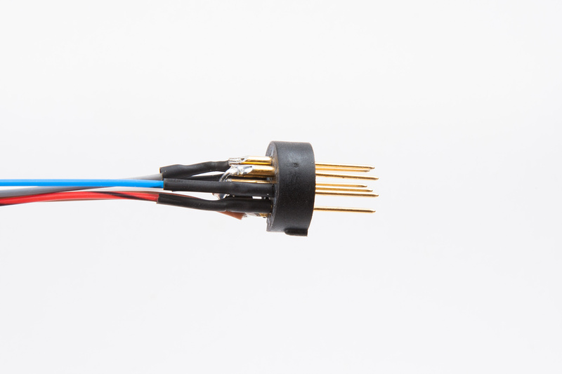
I lost my prior post in last nights forum conversion, so I'm reposting. I have an alctron ht-11a with a broken 7-pin XLR insert. Does anyone have a part number or a source that stocks these? I think the switchcraft QG7M should fit, but nobody appears to stock them.

Thanks :)
 
What you're looking for is the Switchcraft D7M:
http://www.onlinecomponents.com/switchcraft-d7m.html?p=12320347

For a much cheaper Chinese alternative:
http://www.ebay.com/itm/PRO-SIGNAL-PSG01583-XLR-PLUG-CHASSIS-7P-/200760225056


originalmusician said:
I lost my prior post in last nights forum conversion, so I'm reposting. I have an alctron ht-11a with a broken 7-pin XLR insert. Does anyone have a part number or a source that stocks these? I think the switchcraft QG7M should fit, but nobody appears to stock them.

Thanks :)
 
Hi Guys,
I am almost done but have a few issues.

First is on the Microphone Pcb.

Resistors that go in the 14 and 15 spot call for 250M but when I check them with my DMM they don't register.

I have a fluke 23

Also got my AMI T14 today and I think I might have an issue with that too.

When I measure the two red wires I get 20.2 which is ok I guess.  I also did a sound test for a complete circuit and my DMM says it a complete line cause it sounds the signal.

When I measure the two blue wires I get nothin.  Just stays at 0.  And when i do a sound test for a complete circuit the DMM does not make a sound as it is not a complete circuit.

I am I doing something wrong or are these resistors and transformer bad?

Thanks
-Scott
 
Sounds like you have one of the bad batch T14's. You need to contact AMI for a replacement.
 
Banzai said:
What you're looking for is the Switchcraft D7M:
http://www.onlinecomponents.com/switchcraft-d7m.html?p=12320347
Banzai:

Thanks for responding. My prior post wasn't very clear. I need the 7-pin insert that goes into the mic body. I overheated the original while soldering, and it cracked in half. Is there a way to pull the insert out of the mounts you linked? Or is it possible to use one from a mic cord XLR connector?

p1191361704-4.jpg
 
I don't have the part number for you but here's a tip that helps especially with cheaper Chinese connectors.  Plug in a female mic cord or connector while doing your soldering to help soak up some heat and more importantly keep the pins perfectly aligned until they cool.  Sometimes cheaper plastic can melt during soldering and you end up with crooked pins. 
 
Category 5 said:
I don't have the part number for you but here's a tip that helps especially with cheaper Chinese connectors.  Plug in a female mic cord or connector while doing your soldering to help soak up some heat and more importantly keep the pins perfectly aligned until they cool.  Sometimes cheaper plastic can melt during soldering and you end up with crooked pins.
Great tip! When I soldered it, one of the pins ended up slightly crooked, so I attempted to straighten it. Apparently having gotten hot, weakened the material. I barely put pressure on it, and it broke in half. I'll know what to do next time.

I found the Switchcraft QG7M at onlinecomponents. Apparently, they're the only company in the world that stocks the part. Hopefully it fits.  :)
 
Ok so lets see if someone can help me I am using the cinemag transformer I have triple checked all connections everything seems good but I get quite a loud hiss in the mic and when changing polarity it will make a bunch of loud noise before finally settling on the correct pattern and if figure 8 mode the back capsule is defiantly darker, been trouble shooting for about 2 day's now AHHHHHH using a very nice capsule and also electro harmonix tube???

Any ideas
 
Mr.GrinchSD said:
Ok so lets see if someone can help me I am using the cinemag transformer I have triple checked all connections everything seems good but I get quite a loud hiss in the mic and when changing polarity it will make a bunch of loud noise before finally settling on the correct pattern and if figure 8 mode the back capsule is defiantly darker, been trouble shooting for about 2 day's now AHHHHHH using a very nice capsule and also electro harmonix tube???

Any ideas

Clean, clean, clean.  I had problems with the rear side being darker and even though the board looked clean it was even more cleaning that fixed it.  Get ALL flux outta there for starters and then if the problem remains take it from there.
 
So I am getting a new T14 sent out to me.  Apparently mine is one of the transformers with a single strand wire and the newer ones are multi-stranded with multiple wires in it.  The single stranded fail about 10-15% of the time they say.  Don't really know why they sent me one of the older ones but I guess that is the game they play to get rid of old stock.  All I did was open the box and test it on my DMM so do know how it got damaged when it is in padding plus bubble wrap.  Who knows but at least I am getting a new one. Maybe a cold solder joint in the transformer where the wire connects to the winding?

-Scott


Your post was clear, no worries  ;)

And exactly, the trick is to buy the panel connector, then remove the insert from the connector to use in the mic. Everybody stocks the panel connectors (even Mouser), but as you've seen no-one carries the insert on its own.

The D7M is the one I've always used to upgrade a T11. And the one you've ordered will fit no problem.

Good luck!

originalmusician said:
Banzai:

Thanks for responding. My prior post wasn't very clear. I need the 7-pin insert that goes into the mic body. I overheated the original while soldering, and it cracked in half. Is there a way to pull the insert out of the mounts you linked? Or is it possible to use one from a mic cord XLR connector?
 
Mr.GrinchSD said:
Ok so lets see if someone can help me I am using the cinemag transformer I have triple checked all connections everything seems good but I get quite a loud hiss in the mic and when changing polarity it will make a bunch of loud noise before finally settling on the correct pattern and if figure 8 mode the back capsule is defiantly darker, been trouble shooting for about 2 day's now AHHHHHH using a very nice capsule and also electro harmonix tube???

Any ideas

Hard ground the grid with a small temporary jumper wire to make sure you are debugging the right thing.  With the grid hard grounded, only tube self noise should be coming out.  If it's still hissing, then you need to look elsewhere.
 
Would it be a good idea to solder short red and black wires to the 5 and 6 pins on the mic connector so I can make quick  solder connections with transformers that I might swap in and out of the unit?

I know its an extra solder connection that could lead to issues but what is the harm in it if I wrap it up in shrink wrap after I install the new transformer?  Is there a loss of audio quality with an extra solder joint?

 
newbie question but can anyone tell me how the t14 hooks up?    does it matter which red wire to 5and 6 and which blue wire to xp1 or xp2?
 
Hi Flame when did you get your t14? 

As far as I understand this is what I am going to do.  Pick a side on the transformer and mark it as + or - and write it in sharpie on the yellow of the transformer.  That will keep you organized as you keep the windings the same.  On the left red and blue one put sharpie on the wire coating near the bare wire where your are going to solder so that you know which red and blue are from the same side.  You have to keep the sides together.  So if left is going to negative then the right side red and blue have to go to the + connections. 

I have to send my t14 back cause something failed with the blue wires, doesn't show any resistance.  Do you have a single strand wire or multi stranded wire on your t14?

HTHS
-Scott
 
Red wires connect

Pin 5 is audio -
Pin 6 is audio +


The blue wires will connect to the pcb to the terminals labelled  XP1 (+) and XP2 (-).


I tried playing with the headroom of the amp circuit by grounding the grid and watching the output on my scope... funny thing is that the bias is having no influence on the chopped wave form (positive half, do to +/- flip flops throughout?)

The output wave looks nice at real world levels.  The top half of the wave is chopped when I increase the signal source.  I remember another member had the same results. 

Have not been able to get a nice symmetrical clipping.

Now I'm only doing this to fine tune.. the amp circuit is "working fine" (or is it?)...  can anyone verify, with pictures, a symmetrical clipped waveform on the output side of the big cap and at what input voltage etc... thanks guys!
 
Is it possible to use LT1086 adjustable in the place of LM317T without modifications in the PSU? Would be there any improvement in the terms of noise and ripple ? I just have LT1086 adj on hand ...
 

Latest posts

Back
Top