UPDATE:
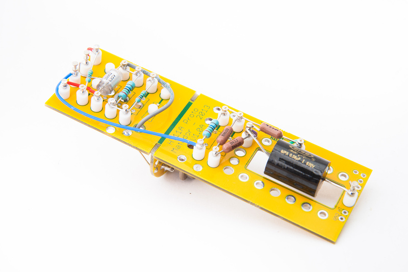
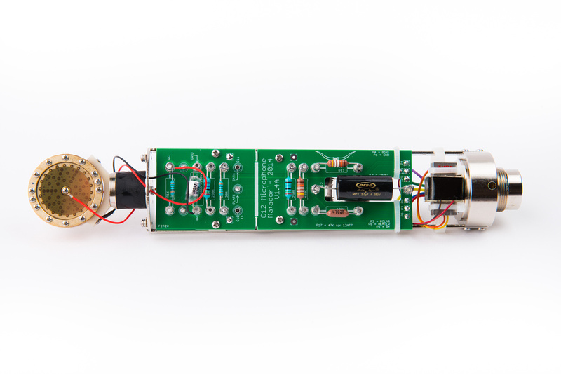
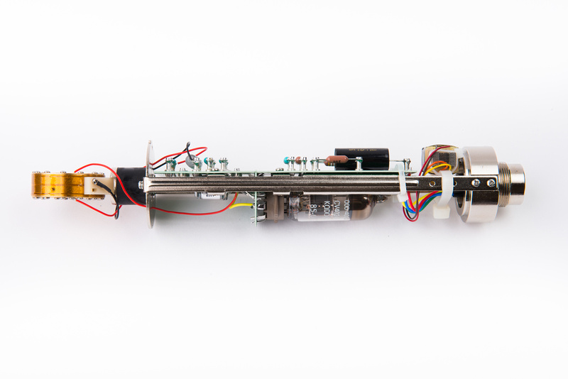
New V1.4A microphone board has been confirmed working on the first prototype build. The layout of the board is familiar and has not significantly changed, but the main improvement is we are now working with a glass reinforced hydrocarbon ceramic board material with electrical performance properties close to PTFE. Matador is the one who came up with the plan and should be able to shed more light on the technical details, but to my understanding.
- HiZ performance when coupled with our existing proprietary solder mask specification should be improved
- very low moisture absorption decreases effects of humidity on the circuit
- white board material base color will render yellow solder mask more vibrantly for superior tone
The new boards are thinner and more flexible than FR4, and there were some layout specifics that needed to be addressed by Matador. These factors required a bit more time and effort to execute than a standard revision on regular PCB's.
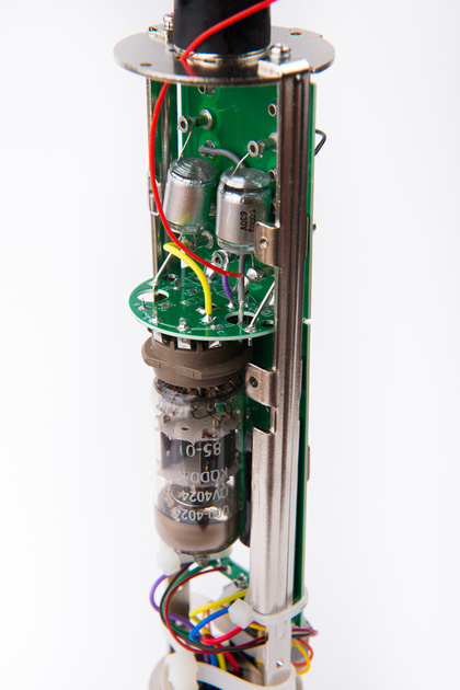
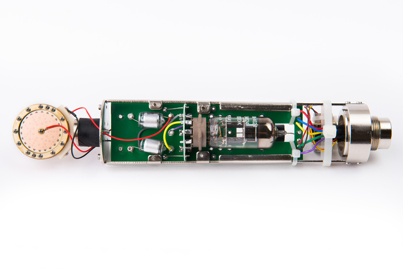
The test microphone was built to use the NOS Mullard 12AT7 tube. I chose to build a hybrid microphone to test in studio with an Eric Heiserman HK47 capsule. Output capacitor is 2uf. Transformer is Cinemag CM-13114.
The current kit standard 68.1K R1, R2 resistors (centered on 6072A tube) were used in the power supply. At full adjustment on the 12AT7 tube, we have 118.5V at the B+, and for now, I am ok to leave it like that because I am extremely short on PSU boards at this time as the production batch of boards has not arrived yet. 33K R1, R2 resistors will better center the trim pot to the 12AT7 tube, but I need to share this power supply with standard 6072A mics.
The mic will be passed off to our affiliate studio for testing to further verify function.




![Soldering Iron Kit, 120W LED Digital Advanced Solder Iron Soldering Gun kit, 110V Welding Tools, Smart Temperature Control [356℉-932℉], Extra 5pcs Tips, Auto Sleep, Temp Calibration, Orange](https://m.media-amazon.com/images/I/51sFKu9SdeL._SL500_.jpg)


