Oktava 012: building a new preamplifier

GroupDIY Audio Forum

Help Support GroupDIY Audio Forum:

This site may earn a commission from merchant affiliate links, including eBay, Amazon, and others.
ricardo said:
Thanks for the stuff on Schoeps mikes.  Its actually the detail design I'm after .. eg the type of caps he uses.  I was amused to find Wuttke used exactly the same RF protection as on the Calrec stick mikes though my circuit (transformer) was completely different from his.  I didn't actually see a pukka Schoeps CMC schematic until this century.

The Schoeps CMC schematic on the web is a very old one via Eric.  Do you know of any later ones or of V4U?

Unfortunately, I don't have any newer Schoeps mics. I own a very old one, still transformer coupled, from the 60s and I *almost* bought a CMT36 (the capsule had problems so I had to return it). AFAIK the newer CMCs still use the same circuit, but I don't know anything about component choices. What surprises me a bit in the older CMC5s and CMT30s I've seen is the choice of polarized tantalums between the FET and both BJTs. Perhaps it was assumed that distortion products would cancel out anyway. I don't know what they use now.

If you're really interested, you could simply shoot Jörg Wuttke an email; his English is very good:
http://www.ingwu.de/index.php?option=com_dfcontact&Itemid=81&lang=en
 
Rossi said:
Mark, you can simply ignore our polypropylene vs. C0G controversy. Either will be fine. Don't focus on the details so much, get some components and try to make it work.
Don't worry, for me is really interesting.

100 nF gives better filtering for the polarization voltage than 10 nF. As you see, sometimes a bigger value is an improvement, sometimes it's worse and sometimes it doesn't make a difference. You have to understand the circuit in order to predict what will happen if you change a component.

Ok a small resume: for C6 a 100nf/0.1uF cap (this one http://www.digikey.it/product-detail/it/ECQ-V1104JM/P4725-ND/10746 )
and for the C7-C8 a 10nF Ceramic cap (this http://www.digikey.it/product-detail/it/K103K15X7RH5TH5/BC1120CT-ND/286742 ) or also here a 100nF?

For the C1 (the Ceramic C0G/NPO this http://www.digikey.it/product-detail/it/RCE5C2A821J0M1H03A/490-7493-1-ND/4277410 ) is ok?
Or one from these http://www.digikey.it/product-search/it?pv3=2&pv17=18&FV=fff40002%2Cfff8000b%2C3400e4%2C1140050&mnonly=0&newproducts=0&ColumnSort=0&page=1&stock=1&quantity=0&ptm=0&fid=0&pageSize=50

Could You recommend these?
Thanks.

 
You can use either type; pretty much any small signal PNP transistor will do. The output stage is a simple emitter follower.

I won't comment on individual parts or brands; this is your project and you have to take responsibility. You won't learn anything if you let yourself be guided through the whole process. Get some parts and try to make the circuit work. Chances are you'll fail the first time. That's not so bad, actually, because you only learn from mistakes. Plain luck won't teach you anything.
 
Ok thanks, but I would really appreciate a suggestion on these pieces... almost a point to start. :D

mark88 said:
For C6 a 100nf/0.1uF cap (this one http://www.digikey.it/product-detail/it/ECQ-V1104JM/P4725-ND/10746 )
and for the C7-C8 a 10nF Ceramic cap (this http://www.digikey.it/product-detail/it/K103K15X7RH5TH5/BC1120CT-ND/286742 ) or also here a 100nF?

For the C1 (the Ceramic C0G/NPO this http://www.digikey.it/product-detail/it/RCE5C2A821J0M1H03A/490-7493-1-ND/4277410 ) is ok?
Or one from these http://www.digikey.it/product-search/it?pv3=2&pv17=18&FV=fff40002%2Cfff8000b%2C3400e4%2C1140050&mnonly=0&newproducts=0&ColumnSort=0&page=1&stock=1&quantity=0&ptm=0&fid=0&pageSize=50
 
ricardo said:
When you do your listening tests on microphonic caps, make sure your test circuit doesn't have anything else that is microphonic as that will reduce the difference between caps.  Just short out the test capacitor and try tapping the mike again.  Actually when you listen to your caps, you will hear stuff quite clearly without having to shout.  Just turn up the gain a bit.
Rossi, if you do try this, could you please put some recordings of the different cap microphonic noise, and also the 'straight wire' test circuit on the web?  MP3s will do.  It's been 30+ yrs since I did the test and was only reminded this Millenium cos Wurcer.

You can just put the test circuit in front of a speaker, play the same piece of music and turn up the gain.  You'll hear differences even with handling noise put playing some music makes the test more consistent.

IMHO, this would be a great magazine article.  A real comparison between parts that people can hear.  Details of gains in the test circuit & preamp etc would be great.
 
mark88 said:
and for the C7-C8 a 10nF Ceramic cap (this http://www.digikey.it/product-detail/it/K103K15X7RH5TH5/BC1120CT-ND/286742 ) or also here a 100nF?
If these are the ceramics on p2 & 3 of the XLR, they need to be 10-20nF.

Bear in mind my caveats about their physical position.

A nice thing about caps that behave like caps should is that are the same from all makers.  NPO/COG ceramics are like that and made using very precise automated methods with great consistency.  Just try measuring loadsa caps from the same batch.  You'll find a nice tight Gaussian distribution though the mean will not be at the nominal.

Conversely, polystyrenes are nearly hand made so maker, construction etc often affect things like microphony.  The value spread for a 1% component is often flat topped which tells you they are selected from a batch.

So for the stuff not on my list, just buy sensible good stuff.
 
I just come back from doing cap tests. I used one of my home-brew circuits, which is very low noise (cascode style input, emitter follower, impedance balanced, thus about unity gain). The cap under test was placed between two teflon stand-offs, one side connected to the DC converter (65V), the other connected to the FET input (at about 5 V).

I tested two different polystyrene caps, a polypropylene cap (Wima FKP-2) and a Ceramic NP0/C0G. I should mention that the ceramic I recently tested in my cap tapping session was (probably) not an NP0/C0G type).

To be honest, there wasn't much difference between all these caps. I didn't use a loudspeaker, and the tests were not carried out neatly enough for publication. I just shouted "HA" as loud as I could with the mic two inches from my mouth, then I placed  the mic one foot away from a cajon, and banged on it as hard as I could. At full gain (66 dB) you could barely hear anything; I had to use an additional 20 dB of digital gain in the DAW to discern the rhythm of the cajon. So thats more than 80 dB gain, which is nothing anybody would ever need for a condenser mic.

I don't know if caps were so much worse back when you tested this or if there was something peculiar with your mic circuit. Perhaps the leads on your caps were long enough to allow them to vibrate. In my test, none of the above caps was remotely problematic; there wasn't much difference in level between them nor was the sonic spectrum radically different. I forgot to test the one mica cap I have in my arsenal.

Perhaps I'll do another run with an additional 47p shunt cap representing the capsule. That should reduce the noise level a bit. But that's not my top priority right now.
 
ricardo said:
mark88 said:
and for the C7-C8 a 10nF Ceramic cap (this http://www.digikey.it/product-detail/it/K103K15X7RH5TH5/BC1120CT-ND/286742 ) or also here a 100nF?
If these are the ceramics on p2 & 3 of the XLR, they need to be 10-20nF.

Yes they are. Thank you!
 
Thanks all!

For the mechanical part, this is the actual project. The body is obtained from a 18/20mm aluminium tube (same as the Oktava preamp diameter; the other two parts (the threaded M18X0.5 and the section glued on the connector, are obtained from a 12/18mm aluminium tube. The parts which will be part of the microphone body will be joint with epoxide glue. The connector has gold plated pins made by Switchcraft Inc. The entire microphone (body + connector) will be painted with a special black paint which resembles the original oktava black.
The pcb will be especially made for this project, so no problem at all for the bigger components (like C2).


32.jpg

30.jpg

33.jpg

34.jpg

35.jpg

xlr_switchcraft.gif

digitalizzato_20140829_1409693140.gif


Suggestios?


-------------------------------------------

COMPONENTS

The actual list has:
Q1 VISHAY-SILICONIX 2SJ305
Q2 TOSHIBA 2SA1015Y

C1    CAP CER 820PF 100V 5% NP0 RADIAL    http://www.digikey.it/product-detail/it/RCE5C2A821J0M1H03A/490-7493-1-ND/4277410
C2    1uF 160v Vishay MKP1839 2.5%
C3-4 CAP ALUM 68UF 63V 20% AXIAL    http://www.digikey.it/product-detail/it/MAL202138689E3/4073PHCT-ND/263276
C5    CAP ALUM 47UF 40V 20% AXIAL    http://www.digikey.it/product-detail/it/MAL202137479E3/4047PHCT-ND/263257
C6    CAP FILM 0.1UF 100VDC RADIAL    http://www.digikey.it/product-detail/it/ECQ-V1104JM/P4725-ND/10746
C7-8 CAP CER 10000PF 100V 10% RADIAL    http://www.digikey.it/product-detail/it/K103K15X7RH5TH5/BC1120CT-ND/286742

R1-2 RES 1G OHM 1/4W 5% AXIAL    http://www.digikey.it/product-detail/it/MOX200001007JE/MOX200J-1000ME-ND/705445
Other resistors chosen with 1% tolerance and 0.25W

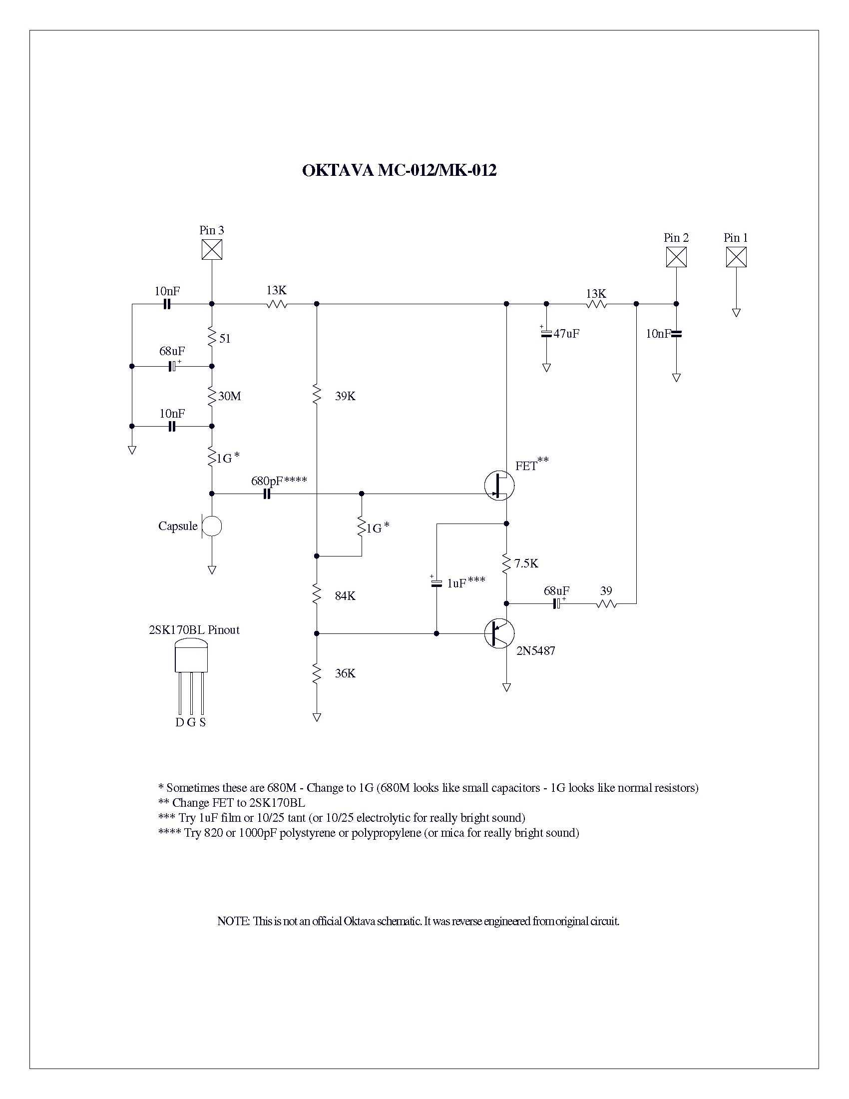
Schematics:
img-2520-1a36567a05.gif
 
Just gluing won't do. The whole body must have excellent ground connection via XLR pin 1.
 
Rossi said:
Just gluing won't do. The whole body must have excellent ground connection via XLR pin 1.
Sure. I will do with some points of solder.
The glue solution is the only way to obtain the complete body I need.
 
A question... I'm moving to Mouser Electronics for the order.

I found some differences about capacitors:
68uF
http://www.digikey.it/product-detail/it/MAL202138689E3/4073PHCT-ND/263276
http://it.mouser.com/ProductDetail/Vishay-BC-Components/MAL202138689E3/?qs=sGAEpiMZZMvwFf0viD3Y3V75KleFm5GEaVTx0jtLXcU%3d

100nF
http://www.digikey.it/product-detail/it/K103K15X7RH5TH5/BC1120CT-ND/286742
http://it.mouser.com/ProductDetail/Vishay/K103K15X7RH5TH5/?qs=/ha2pyFaduhe00q0fZhzTXSO5XL/4BQFovo4aGbrcHLrtvyidDC%252bNw%3d%3d

The code of the producer is the same, the capacitor should be the same, I think its only a problem of Mouser images, right?


And is best using two 1GOhm resistors in series or one 2GOhm resistor? The nominal voltage from 500V to 2.5KV is a problem?
thanks
 
mark88 said:
And is best using two 1GOhm resistors in series or one 2GOhm resistor? The nominal voltage from 500V to 2.5KV is a problem?
I would use just ONE 1G resistor.

The Oktava won't benefit from 2G and the construction of 2G from 2x1G in the article will probably introduce LOADS of problems.

If you can get cheap 2G, use them .. but bear in mind you will need to be TWICE as clean with your construction.
 
ricardo said:
mark88 said:
And is best using two 1GOhm resistors in series or one 2GOhm resistor? The nominal voltage from 500V to 2.5KV is a problem?
I would use just ONE 1G resistor.

The Oktava won't benefit from 2G and the construction of 2G from 2x1G in the article will probably introduce LOADS of problems.

If you can get cheap 2G, use them .. but bear in mind you will need to be TWICE as clean with your construction.
thank you.

a question: in case I would like to amde a smaller pcb, which capacitor should I use to replace the C2 Vishay 1uF 160V MKP1839?
this would be ok?  http://it.mouser.com/Search/ProductDetail.aspx?qs=MnmR%252b%252bqUg%252bqj59hv2%252bTJiw%3d%3d
or another type of capacitor?
 
mark88 said:
a question: in case I would like to amde a smaller pcb, which capacitor should I use to replace the C2 Vishay 1uF 160V MKP1839?
this would be ok?  http://it.mouser.com/Search/ProductDetail.aspx?qs=MnmR%252b%252bqUg%252bqj59hv2%252bTJiw%3d%3d
or another type of capacitor?
Even the original electrolytic is OK.  It's non-critical.
 
The project is still going... this is the pre-design of the PCB: to understand how big could be using also the big C2 capacitor (Vishay MKP1839 1uF 160V).
C2 and C5 are on the bottom side.

rev1.2_01.png


rev1.2_03.png


rev1.2_02.png
 
Sorry, but i didn't read entire topic. Maybe it will be usefull for someone. I saw few days ago that someone is selling blank PCB for 012 on ebay.

Cheers
 
ln76d said:
Sorry, but i didn't read entire topic. Maybe it will be usefull for someone. I saw few days ago that someone is selling blank PCB for 012 on ebay.

Cheers
They have radial capacitors instead of axial ones on C3/C4/C5 so you can't use the capacitors suggested by Scott Dorsey. So useless.
 
A question: I'm moving to more economic resistors for R1 and R2. Which differences are between thick film resistors and metal oxide resistors? thanks
 

Latest posts

Back
Top