OPAMP upgrade for LM301AN?

GroupDIY Audio Forum

Help Support GroupDIY Audio Forum:

This site may earn a commission from merchant affiliate links, including eBay, Amazon, and others.
You could probably pick opamps with a dart board and do better than LM301.. As I recall they could be made a little faster using feed-forward compensation (only in inverting mode), so if there's an odd looking cap from the - input to one of the compensation pins, remove that.

Depending on the specific circuit a 5534 compensated for stability with the closed loop gain as used should be fine. I think the 5534 can be used without compensation for noise gains > 3x or so.  Only if it's used unity gain non-inverting does it require full compensation.


JR
 
Dualflip said:
Hello ppl, i have a studer 169 module and i've heard a lot of ppl upgrading the opamps on this ones

Hi Dualflip,
where do you've heard that?
I'm asking because I'm curious about the details of this substitution..

I've asked here some months ago the same exact question:
Studer 269 - worth replacing LM301s?

After that, I've started to fully recap the 269 I have.
I am so happy with the sound, now, that I've stopped with the opamp replacement issue.

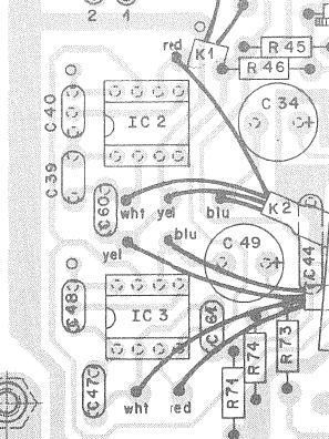
Btw, the 301 opamps in these consoles, in the input and summing sections [I am not talking about the "treble-bass/presence" eq and master limiter sections],
have their internal input stages replaced by transistors [see pins 1-2-3], as Samuel Groner pointed out in the thread linked above,
so swapping these may become tricky.
Studer 169-269 input/summing no-input opamps
[pag 1 input module, pag 2 master module]

And here are the complete schematics of input and master modules:
Studer 169-269 input/summing complete schematics
[pag 1 input module, pag 2 master module]

So, for the eq and limiter stages, the interesting thing is that all the 301s are socketed, the bad news is that you must at least remove some caps, if I've well understood
[or maybe bending the compensation pins of the new opamps].

P.S. These Studers are also fantastic for their hackability..
I've just a stupid project of using the 3 signalling banana outs of each channel for feeding a nice tape Studer meterbridge I have, made of 16 Modutec VU-meters.
 
Don't touch the op-amps with separate input transistor(s). That trick is used to bypass the first stages of op-amp. It doesn't work with a 5534. And there is nothing to replace. The performance is actually quite good.

It is much better idea to replace those 301 op-amps that are used "alone" (like eq if I remember correctly). 1. Remove all capacitors used to compensate the 301. 2. Bend the compensation pins of the 5534 upwards and solder a 22p capacitor between them.
 
The compensation caps are typically small, tens of pF but IIRC the feed forward compensation cap from the - input to compensation node was around 150 pF.

JR

 
Dualflip said:
Both opamps have more or less the same cap and connections, so which one do you mean it has to be removed?

I am not sure if your question was for me...

Remove caps C39,C40,C60,C47,C48 and C61. Connect a 22p ceramic capacitor between pins 5 and 8 of NE5534. Now you have replacement for IC2 and IC3.

In this case you dont have to turn pins 5 and 8 upwards since pin 5 is not connected in the PCB (or it wasn't in the mixer I modified but it is still a good idea to check).

 
Thanks a lot, audiox, I was writing the same, but was unsure about C60 and C61.

Anyway, Dualflip, good news:
If your PCB is like this one [much likely], you can use the two not connected holes around C40 and C48 [they goes to pin 5 and pin 8], replace the 2 caps with two 22p, and remove C39 C47 C60 C61.

studer_input_PCB.png


It seems that people at Studer have made the PCB ready for opamps replacement?
 
1954U1 said:
If your PCB is like this one [much likely], you can use the two not connected holes around C40 and C48 [they goes to pin 5 and pin 8

I didn't notice that. Good to know.

1954U1 said:
It seems that people at Studer have made the PCB ready for opamps replacement?

Just a good design practice. Since there is space on the PCB, it is a good idea to allow all kind of compensation schemes. It costs nothing to add a few extra holes but can be a huge help if you have ordered thousand boards and find out that the circuit oscillates even though the prototype worked fine. Or the manufacturer discontinues the op-amp. Or something else.
 

Latest posts

Back
Top