Orange 86 Build Thread - no PCBs for sale

GroupDIY Audio Forum

Help Support GroupDIY Audio Forum:

This site may earn a commission from merchant affiliate links, including eBay, Amazon, and others.
I read that shunt voltage regulators are not recommended to include no load.

Oa2 is a shunt regulator, so when heater is switched on simultaneously and B +, Oa2 works for a while in the limit mode. Then, when the EF86 and E88CC are warmed up, the Oa2 regulators enter the normal mode.

In order not to create an overload problem for Oa2, I apply voltage to them later when the EF86 and E88CC are warmed up.

I also read that the zenner regulator with a transistor can work without load.
Therefore, I wanted to remake my power supply, which would simultaneously turn on the heating and B + one switch.

But maybe I'm wrong and I do not understand this correctly.
 
Here's a snap of my Orange86 build ....  in a 'low-THD' scenario ...  unity gain .. 2 notches up on the 'gain' rotary (pos 3)

I found the 6N5P to be the lowest THD of the 'au7' types I rolled  ..  the highest was the 5814 then 12AU7 then 6829 and 6N5P best by quite a bit  ...  headline figure of 0.096%

All 5 of the 6J32P measured virtually identical and when looking at the pentode plate,  THD is even lower.

I used an Edcor wsm 10K/10K line input transformer to debalance (no pad), which itself adds around 3dB of EM induced hum components, and something like 0.015% of h3 and higher components to the THD bottom line.

So, when using the DI (direct input), one can expect even better numbers.

Also, I have somewhat lower gain overall, due to the large stepdown at the output traffo ...  15K or even 8K is probably more typical and would alter the numbers somewhat, but not the basic 'signal-hum' margin.

My heavy-cast-shield Trimax output transformer is invulnerable to psu EM  8) 8) 

Like it's famous over-engineered US bretheren from the day, it is near perfect in that respect ..  orientation makes not the slightest difference. It's literally 'like a shield of steel'.

...

Also to note, with a higher input signal, the numbers improve somewhat until THD starts quickly rising as the pentode begins grid conduction (well before the notional -1.0V bias line is reached).

So - quite a good basis for further optimisation  :)
 

Attachments

  • Orange86 pre line input unity low thd 6N5P baseline03b.png
    Orange86 pre line input unity low thd 6N5P baseline03b.png
    316.1 KB
Glad this thread is picking up steam again.  Mine is far from done but thanks to Charles I got the front panel almost done, helped sooooooooo much.  I decided to go balls out on this build so it has the AH cinemag trannys on the output and im gonna outfit this first stereo build with telefunken EF806s tubes up front and E88CC teles in the back.  Figured this build is 3 times what i expected already so might as well finish strong  ;D
 
It's a very satisfactory circuit config and very forgiving of stuff  ...  for the 'less is more' thing, it's an archetype.

If I were going all out, it would be p-p wiring, external ss psu with error-amp based regulation for HV, well-shielded transformers and  some choke loading for V2. An output attenuator after the traffo is essential imho, to  really drive the thing to perfection.

All that would probably drop the noise floor around 6dB  with some additional gain to boot ...  I think a low-THD  'signal to hum' margin of 100dB in typical use would be doable  ..  perhaps more.

In my 'measurement world'  ...  background 'psu hum'  is  -130dBFS,  op-amp circuits come in at -120dBFS  and my very best tube circuits (so far!)  do around -115dBFS  in typical use scenarios - ie. a good cathode-follower circuit.

My basic or 'unity gain'  Orange86 hum floor is around -114dBFS more or less, with direct input and plenty of nfb (pos 3)

I give the 'dBFS to dBu' conversion factor and the 'headroom available' in my attached snap, along with the THD ..  in an overall unity gain, low THD  scenario. 

....

The great hum performance comes into it's own if you connect up a tube limiter or eq ...  it can make the difference between needing a noise gate or not, remembering that tube limiters 'silence' scenario adds something like 6 .. 12db of gain  typically (even more when pushed) and thus increase noise, mostly hum.   

Driving my build of a 660 type, the Orange86  shines where others have not  - and my pM660 is actually pretty quiet as far as tube limiters  go.

My own builds of the classic passive eq with tube makeup line amp adds a good dollop of hum with the bass boost enabled! I'm re-doing them now with ss make up amps  :-\  to get them usable - a case of insufficient shielding of the 'filter section'  - combined with the usual dross that most any tube build with unregulated and nearby  psu traffos, especially the non-toroid types,  excel at.

It's always that 'last couple of dB' which tips good into great.

...

THEN with the magic tubes ... certainly a good 6SN7 for the output  and for the pentode,  ...  I have a 'reasonably' healthy skepticsm about special quality nos, but I'd dearly like to try some of the fancier types ... the siemans, telefunkens, mullards et al!

I'd also open the field up to the non ef86 types ..  there's some notable ones to try  8) I like the humble 6AK5  ..  I've used it in tube mics, and tube DIs ...  very stable and quiet with a surprising range of applications that belies it's small form factor.

Its about the only alt I've tried that has similar or better perf to the even more humble 6j32p. I like some of the older octal pentodes no doubt, especially the metal cans .  but they can be a little twitchy compared to the later small glass types.

...

However for now, my  humbly-tubed and knocked together  Orange86  build is my 'most used everyday'  ... just plug into DI and pretty much every guitar type does a quality job ..  bass, elgtr, jzgtr, acgtr  etc  ..  studio ready characterful but clean sound.

My personal fav is a 'Champ' style (small single 6V6 single ended instrument combo) that I added a simple attenuating 'Line Out'  connection  ...  running that to the Orange86 'line' input with the edcor 10K/10K giving quality isolation.

....  and thence off to the mix and speakers with some ambience reverb ...

You get the gruff Champ sound on the hollowbody, including feedback ..  with the solid sound from the mix monitors  ;D

I did mod the Champ for low hum .. with a variable nfb control and a psu choke ...  av7 + 6K6gt tubes

....

Here's a snap of my current tube stage of interest ...  a 6u8a 'white cathode follower' as in the la2a limiter output stage,  but with no nfb or gain ..

It's a good starting point .. for the chisel-ing away ...  this is the line amp of my build of a 'deluxe'  .. ie. a p-p 6V6 instrument amp head with a proper balanced line out amp. The 6jw8 does the same thing, with less thd if you can do 250V supply  :)

I'm hoping to refine it some more, to about half the thd,  but it's pretty good for a tube rectified,  choke-filtered psu (unregulated) with dc filtered heaters.

It illustrates the observation that the Orange 86 preamp, with 2 gain stages and a nfb gain control is only a fraction more shmutz than a super-simple cathode follower,  as well as a lot less thd.

The kicker is that about a 2cm displacement of the psu traffo towards the front would have given me an additional 2.5dB improvement in hum ..  due to the placement of the large-ish 6v6 pp output traffo in between the edcor psu traffo and the utc a series line amp traffo.

Too late - already drilled ...  but there you go ..  potentially even more high perf in a small-ish amp head with a big-noting line amp.
 

Attachments

  • 6U8A wcf unreg choke+cap B+ dc heaters unity baseline 01c.png
    6U8A wcf unreg choke+cap B+ dc heaters unity baseline 01c.png
    237.2 KB
Thanks for the info AlexC


In my experience Edcors add quite a bit of distortion.  This is with cinemags , Tesla ef806 and JJ e88cc.. Another MOD is  Local FB resistors  R9 to 3M3 and R8 to 220K  will provide 4 more dB gain.  However, my reason for this mod isn’t necessarily for more gain, but more uniform frequency response across amplification settings.  At high gain levels the bandwidth decreases  and the standard circuit starts rolling off the highs at 16K or so.  So the mod will give flatter response from 20-20KHz up to 46-48 dB.

My next mod will be a high cut switch. We could limit HF response with small caps across the global Negative Feedback, however I think it would be better if the user chooses the high frequency response desired. I would especially want to mellow out the female singers’ sibilants or make a brass instrument more mellow. And of course if you’re using a mic with limited range, then of course rolling off highs would be fine too.
 

Attachments

  • C5A59431-86FB-4839-987A-70C949BE41EF.jpeg
    C5A59431-86FB-4839-987A-70C949BE41EF.jpeg
    393.4 KB
The cinemag line up is surely very good quality, range ( and price  ..  at least in the recent past ) ...  ;D

I like the tube mic unit .. Cinemag 2461nico  .. I used it in my big tube mic ..  during testing, without a capsule, I was really floored by the sound of the cinemag nico ..    the mic got done :)  and a I bought a couple more from mr Banzai ... for use in a couple of tube DIs ..

They have the most  impressive response  for clean and with the pleasing  'warmth' at higher drives.
      instrument -> DI traffo -> 6AK5 pentode-in-triode-mode -> 2461nico -> xlr balanced out  at moderate line levels

I'm using a typical cheap tube mic  external psu,  modified of course!  and all in all, it's not much different from the mic I built - just replaced the capsule with a DI traffo.

Cinemag really should offer it with one of their nice shielding cans! Its a memorable sound.

..

Also,  I did do some freq response sweeps on the Orange86  line input from above

I found it was flat -flat  basically +/- 0.2 dB over the 20..20KHz bandwidth, with pretty much all the level I thru at it ..  up to -4dBFS or +13dBu. Phase response was similarly 'nothing to see here'.
 
Good stuff Alex. You’re using the mic transformer as an output?

I fine tuned the the fine gain switch to a range of +/- 5 dB

Using these values in place of R5 and removing VR-1 and R17 pot adjustment that alters the lower feedback divider resistor.  These values are from stringing series resistors together like on the gain switch.  It should give  a 10 dB range with 1/2 a dB between steps other than the 200R step.

You can wire with switch from several points:
the 2 R5 PADs
R17 - provided one side meet the feedback of the fain switch
or Just take it from the V1 connection on the gain switch and the other end directly to ground.
-a look at the scheme should clarify this


36
44
57
70
80
90
100
112
124
136
154
197

Using series resistors:

36
8 (2 16R parallel)
13
13
10
10
10
12
12
12
18
43
 
guavatone said:
Good stuff Alex. You’re using the mic transformer as an output?

Yep!  Alongside my Orange86 preamp, and completety seperate  (sorry for the confusion! - I can run my posting too fast at times) 

..  I have an 'active DI' build ...  basically I bought a cheap tube mic setup ...  then I modded the psu to 'dual purpose'  with my own 'active DI' box, build in a cheap sino alu small case.

The 'active DI' circuit is basically the same as the tube mic, as I modded it ..  instead of a capsule, I put in a 'di traffo'  ..  a Jensen in this case ...  the 'head' amp is the same ..  6ak5 + 2461nico  ..  it gives a 'moderate' balanced output on the xlr  ...  not proper 'line levels' but much hotter than a tube mic!
 
And just while I'm confusing things some - if I were to do another Orange86 channel build, I would make the external psu with a typical 'tube mic' powering capability  ....  would be really great to have a proper tube mic powered up without the usual psu box.

Just a thought, in the interests of reducing psu boxes! and sometimes, the noise bottom line  ..  in general terms.
 
There’s a manufactured REDD mic with the 2 tubes in there. I’m curious how long it will be for them to get toasted from heat. I’m surprised that they seem to be running the relatively high impedance line through the mic cable. It hurts my head having 2 transformers between 2 ef86’s, the way you are talking about doing it, but why not....

A single channel orange can handle the extra current of a tube mic with DC filaments.  Maybe a  paralleled 12at7 cathode follower or a mu follower with very health  input z of 6M and output z of  260 like here:

http://www.valvewizard.co.uk/mufollower.html

Why are you making me think AlexC ;-)

-back to slugging poles. Er that doesn’t sound good. But that cap needs a home.
 
guavatone said:
A single channel orange can handle the extra current of a tube mic with DC filaments.  Maybe a  paralleled 12at7 cathode follower or a mu follower with very health  input z of 6M and output z of  260 like here:

http://www.valvewizard.co.uk/mufollower.html

Everyone  loves the 'valve wizard' merlin, why not!

I think Steve Mariot said it best back then .. 'it's all too beautiful.'

:)
 
I made my 'fancy' pentode choice for my next  'interpretation' , point-point,  of the venerable redd / german type pre-amp ..  made accessible  by the Orange86  work.

...

On spec and as yet *without* testing ...

I went for the e83f  ...  tall-ish bottle, mesh grid, 300mA 6.3V heater, moderately high gm at 8200 umhos, 2.1W max Pd plate, with a 210V max Vscr and Vplate  ..  designed for 'telecomms' work  ..  has a specified 'hum voltage' figure ...

In this case, amperex/sylvania branded holland e83f, probably philips manufactured, gold pin 'special quality' ...  8)  around 10usd each with distant delivers ...    for a tested bunch of 8 off - enough to get 4 close matched and a couple of good spares.

All that and sure,  I'm a big fan of the netherlands in general  :)  but the sixties and seventies in particular, would have to have been a real experience ...  electronics *tube wise* speaking.

...

Obviously, it (e83f) has a different pinout than the ef86  ...  but for a point-point build, all good! 

nos ef86 were just 'too damn expensiv' and I'm not confident of my chances  'bettering' the humble 6j32p  with one-off or pair buys that I could afford. Forget about bunches for small $ - those days are long, long gone. The nos examples I looked at seemed to be of less-than robust looking internals!

...

re the e83f - it's known for its use in the german v76 preamp, but there it is an output pentode! not the first-stage as I plan to use it.

Comparing with the ef804 pentode, which is used in the v76 first-stage, the differences are the e83f has the higher heater current and also a significantly higher gm. The rest is pretty similar. The ef804 is yet another pinout! and it costs even more than ef86  :eek:

The higher gm of the e83f can be a negative, in the sense that it can potentially increase microphonics;  but a positive  in that a higher gm should result in lower noise (at least in triode mode) and may also provide increased sensitivity -  useful in some circuits.

In my case, I wanted something moderately high in gm because I also want to use the e83f in my latest limiter build, middle position. I reason that a 'special quality' unit with good construction will also be very usable in the first position of a mic pre.  The e83f can  also deliver a decent amount of current at moderate plate voltages.

...

At the line-amp end of things, I'll likely be doing  a parallel'd stages 6SN7 triode with choke loading, but I will try a 6V6-triode-mode as an alternative ....  one can get quite decent perf from these in a line-amp config and I'm keen to compare.

Transformers will be some old rca 20k/600 at the output, some jensen 10k/10k for line input,  and some utc ouncers for mics ..  something like 250/5k I think.

All have good-to-best shielding, which is great, but this is an externally powered and regulated HV, so should be really extra quiet.

The quest is on .. to 'better' the humble 6j32p/6n5p combo of my Orange86  :D :D  Tally ho!

...

Winter's nearly over and the diy season is off to a good start, having finished and installed a nice, tall, solid pine rack to house all this great tube gear!  Affordable 2cm pine biz with tung-oil finish .. cost me around 70usd or so all up.

I'm still up to my elbows in redo #4 of my 'deluxe'  ...  a  pp 6V6 inst head + wcf line-amp  (of above pic)  ..  getting there slowly ...  every move now is a watch on 'hum' and 'thd' ....  but I will prevail!
 
And my Orange86 is back on the bench  :)  trying out some mods    and once again  attempt #3 of an eq+makeup  module    ..  worthy of inclusion.

Not ruining the stellar noise perf of the stock Orange86 is my main focus here  ...  not easy to do with a passive eq, even with a lower-Z scaled stack and the most minimal of gain make up stages.

If necessary, I can go to solid state. I need an eq!

...

My Orange86  will  also  'power' the prototyping of this new  'e83f/6sn7'  combo while I dial in the perf.

This will be first time I have bothered to knock up a prototyping 'rig', where I can easily vary the operating conditions of the first-stage pentode, while watching the THD+N displays provided by the 'REW' application ...  (Room EQ Wizard real-time-spectra).

ie  ...  varying the cathode bias voltage, plate loading  and supply voltage  .  plus  the input signal  characteristics.

It's a lot more time consuming than  ... 

Trioda loadline simulations ...    http://trioda.com/tools/triode.html

Dang I love that site and the effort behind it  :-*
 

Attachments

  • E83F SQ gold pin Amperex Holland.jpg
    E83F SQ gold pin Amperex Holland.jpg
    140.8 KB
Just a warning about the new production Tung-Sol JJ ef806s.  I would advise against using these in the REDD circuit.  I was seeing some funky readings on the AP, where the gain was changing enough to make me wonder.  Sure enough the Plate was at 82V and the Screen at 100V.  These should be at 75V and 85V respectively.  So far new production e88cc’s seem fine.  Pentodes need g2 to bias the tube correctly and somehow it seems new production tubes have missed the mark. They will “work” but sub-optimally.

I plan on blogging about mods, but for now I'm ripping out those Compensation caps and boosting HF a bit in order to get a fairly consistent Frequency response to 18K with -1 dB at 20-21K across all feedback settings.

1.  Omit C-FB-1 & C-FB-2

2.  C-M1 - Put a 270-300pf  ceramic COG/NPO cap from V1 grid(Pin 9) and use 1K on R3 grid stopper

3.  C-HF1  Put a 22p COG/NPO cap rated at 1KV across R8. 

IMG_2269.jpg

https://www.dropbox.com/s/p3jugxio9f96e8u/IMG_2269.jpg?dl=0

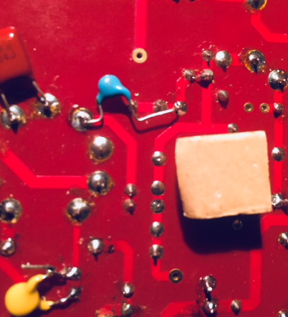
It takes all of 5 minutes and is pretty easy.  The blue cap is the 22p and ones side goes into the valve PAD which has plenty of room and the other side goes into C3's bypass cap pad.

The Yellow cap is the 300p cap the top wraps around the lead of the 1K grid stopper and the bottom lead going into the ground pad for R2, which is not needed.

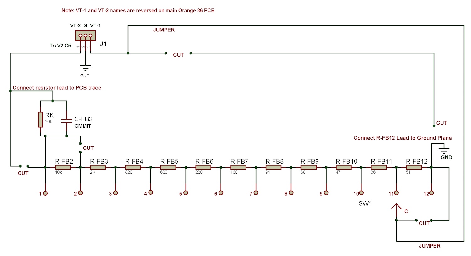
With the above complete here is the Constant Impedance Gain Switch Directions
-Above mod necessary for Constant Impedance Gain Switch

1.  Jumper R-FB-1

2.  Omit these Parts

C-FB-1
C-FB-2
R-17
R-5
VR-1

3. Follow schematic of Gain Switch Connections

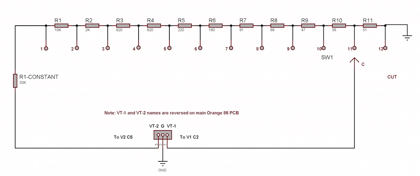
Here is the basic Diagram without the Gain Switch PCB:
Gain%20sw%2030k.jpg

https://www.dropbox.com/s/vqzx9pvux8wq3x8/Gain%20sw%2030k.jpg?dl=0

Here is the Gain Switch Modification diagram:
Gain%20sw%2030k%20PCB%20mod.jpg

https://www.dropbox.com/s/ifymtwdoqcxtnv3/Gain%20sw%2030k%20PCB%20mod.jpg?dl=0

My definitive termination configuration for Input transformer secondary is  130K for R-T
For DI-L a 2M-4M  resistor.  And omit R2. Use the appropriate R-z and C-Z depending on the transformer used.

The 130K will reflect 2K at 1KHz and 1.5KHz at higher frequencies.

Also, if you want to cut your high frequency response you can play around with the blue cap from 47p-100p for +1 dB or so from 5-10 KHz.

Notes on removing Feedback caps and adding the 2 caps in MOD above:
To make a long story short, the higher gain settings with less feedback have less highs.  Once feedback is increased HF response improves.  So we take care of the frequency response before the amp and nested in the amp without boosting HF in the feedback loop which I think degrades the sound and creates phasing.  I was recording at 98K and something about the high end was bothering me, which is what lead me to this mod.

And That Damn Fine Gain Stupidity

I also recommend this:
Remove  R-17 and VR-1. Then Replace R-5 with a 82-100R.  The lower R-5 the higher the gain of V1, albeit a very small amount. You can probably get away with 43-75 Ohms but YMMV.
 
Marc Duchesne said:
I used the squich pot, still need to install a bypass switch as suggested.

rather than a separate switch, there should be many options of a 500K pot with switch that opens when you start turning.  or those push-pull combo switch pots.

$3 here

https://www.tubesandmore.com/products/potentiometer-alpha-audio-spst-switch
 
Attention builders! I just redesigned the gain switch that adjust negative feedback with a constant impedance at 34K.  It’s like the gain switch for the ubiquitous V76 preamp. It should give better performance than the original design. I will post details soon.
 
New gain switch added to Page 1 on Thread.  Probably easiest to just use a solder tap rotary 12P single deck MBB switch
.  BBM won't be too bad

Last switch setting fully bypasses V1's Cathode and disables global Negative Feedback.


C2 should be 220uF BP/NP 16-25V cap.
 
Thought I'd post to keep this thread alive.

I'm actually working on a build, but it has been on hold while I wait for transformers. That has been a comedy of errors -- I ordered them over the summer, paid in September when they realized they hadn't made them for me and finally got it all sorted, then they shipped them to an old address (I've done business with Cinemag before so they must have picked the wrong address from their files).

Anyway, I should have transformers next week so I'm back to thinking about this. Hoping I can get my case sorted by Thanksgiving and finish up the work over the long weekend.

Charles and I had some nice chats in April when I was first thinking about doing this, so I think I have an idea of what I want to do for the feature set and power supple. But I guess I should look at the new gain switch design, too.

Been using APIs and some Focusrite pres with some lovely flavors between them, and this is lovely in a very different way. Should be a useful addition to my project studio in addition to a fun build -- and I mostly build crap because I like building crap so... 

Fingers crossed, pics in December.
 
Sounds good Goose. I just finalized a mod to the gain PCB to make the constant impedance gain circuit. I’ll try to post it soon. 

Good prices on non-shorting Grayhills here

http://www.alltronics.com/cgi-bin/item/28B149/search/Grayhill%2DRotary%2DPCB%2DMount%2DSwitch%2D1P%2C%2D1D

 
Moose dont feel bad i ordered a set and it took about 4 months to get until i called and called then they had em out in 2 weeks.  Right now im on hold for a second pair but its just taking too long and am thinking of going with sowter next time.
 
Happy New Years Team DIY!

You will see these changes in the first post.

I just updated the BOM and hope it makes building and ordering parts easier.

I also made some refinements to make a more definitive build based on this past year of tinkering and measuring on the AP

We're really excited about the Constant Impedance Gain Switch which should make these preamps sing at very low THD across
all gain settings.  The highest gain setting having zero Negative Feedback.  The Feedback/Gain circuit will be similar to the V76
and Lorenz topology.  It will not add High Frequency boosted, reversed polarity signal to the EF86's Cathode.  Instead we slug the
HF pole before the EF86 input so it doesn't need to be compensated after the fact.

OTHER UPDATES
Recommend R5 or 120R and omit VR1 and R17 network.  IMHO a waste of $2
R-T = 130K (list of reflected Impedance on BOM sheet)
DI-L = 2M
Omit R2
R3=1K (can't hurt and may help)

Edited and added non-Kit Part options
Yellow Highlights for non-Kit Parts for better clarity
 
Back
Top