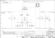
P48 from DCDC converter advice

GroupDIY Audio Forum

Help Support GroupDIY Audio Forum:

This site may earn a commission from merchant affiliate links, including eBay, Amazon, and others.

adamasnan

Well-known member
Joined
Sep 24, 2018
Messages
139
Hi all - let me start by apologising if this is covering old ground here.  sorry!

I am currently starting to build enclosures for my vintage German broadcast amps, a couple of Tab v372, a couple of Siemens v272, and Neumann PV46D for now.. The latter has actually been completed and I have placed a DCDC converter (24v>48v) and the  circuit based on this scheme (figure 2) https://sound-au.com/project96.htm. But I may have bodged it a bit..

It works, and on a good day is very clean, but recently I noticed sometimes, with some mics, there is a more noise on one channel (always the same channel, not the mics, not the preamp). I am using a 63v 220uf cap at C9 instead of the specified 10 uf (???) which eliminated the noise of the DC converter very well, on first multiple listens and comparisons. I ma using blocking caps of 50v 22uf, and the zener network as illustrated, but I don't really know how to improve upon it without guidance, I am very good with a soldering iron, but very noob with actually circuit logic.. I have seen other designs using 63v 100uf caps for blocking as well as DC filter..

Can anyone help me optimise this whilst being as economical as possible (i.e. not adding too many extra components)

Many thanks!!!!
 
What DCDC converter are you using? Cheap DC converters could easily be noisy. Even high quality ones will emit a whine when the load is not enough and so the switching IC throttles. Adding larger caps is not a good idea. There are instances where larger caps will put stress on surrounding components.

The proper way to do this IMO would be to just get an appropriately sized, high quality 48V ACDC SMPS followed by a large choke and small cap to filter. Phantom return is through the chassis (usually) anyway so it makes sense to just make the 48V completely separate from other supplies. It could be that your DCDC converter is leaking noise backward into your 24V supply.

But it's not completely obvious that your DCDC converter is actually the problem. You claim it's just one channel but the other channels are ok? It seems more likely that if there were an issue with the phantom supply, that it might affect all channels.
 
Hi Squarewave, thanks for the comprehensive reply!

squarewave said:
What DCDC converter are you using? Cheap DC converters could easily be noisy. Even high quality ones will emit a whine when the load is not enough and so the switching IC throttles. Adding larger caps is not a good idea. There are instances where larger caps will put stress on surrounding components.

I am using this - https://de.rs-online.com/web/p/dc-dc-wandler-isoliert/1874619/

Adding larger caps to which part, the blocking, or filter (C9)?

squarewave said:
The proper way to do this IMO would be to just get an appropriately sized, high quality 48V ACDC SMPS followed by a large choke and small cap to filter. Phantom return is through the chassis (usually) anyway so it makes sense to just make the 48V completely separate from other supplies. It could be that your DCDC converter is leaking noise backward into your 24V supply.

Ah but the thing is I prefer to power this stuff from 24V battery pack/s for multiple reasons, that's why I am using a DCDC converter. I was previously using standalone P48 supplies (DC powerable) but I really prefer to carry less boxes and patch cabling..

squarewave said:
But it's not completely obvious that your DCDC converter is actually the problem. You claim it's just one channel but the other channels are ok? It seems more likely that if there were an issue with the phantom supply, that it might affect all channels.

There's definitely a difference between them, I think most obviously with using Sennheiser MKH30 on that channel. Then sometimes, clean with other mics (Schoeps CMC5 for example.. and I did check the output voltage it's 47.5V) The noise is not high, but definitely detectable.  Is there anything you could suggest that I alter in the existing circuit? 100uf cap for filter? BTW I didn't use the 10ohm resistors in that circuit either, but maybe this helps?
 
Have you tried looking at it with an oscilloscope? Perhaps you could post some pics. The nature of the noise should give you an indication if its your DC to DC converter or something else.
 
Adding much larger extra capacitance on the output of a DC/DC converter might compromise the stability of the feedback, or at the very least, extend the time it's supplying a virtual short-circuit on startup.

For better filtering and added safety, you'll want to add an inductor (no more than  100uH, and of suitable current rating) between the converter output and your bigger additional capacitor.
 
That DCDC converter looks good. It's the right size at only 125mA and ripple is low.

But feeding it from what is supposed to be a clean 24VDC supply is a potential point of failure because the switching element is sourcing current in a way that could bleed noise backward into your otherwise clean supply. Fortunately the SMPS doesn't need 24V. The datasheet says it can make 48V with as little as 18V on the input. So you could make a simple capacitance multiplier circuit like this:

transistor-capacitance-multiplier-01.svg


You'll loose a volt or so but will still be well above 18V and it will isolate the two supplies. Note that you cannot use just an RC because, with enough current drawn, the voltage might drop below the requisite 18VDC.

Also, if you only have 1-2 phantom loads, you might need a load resistor across the SMPS output to make sure it's not going into "hiccup" mode. Maybe a 4.7K resistor to sink another 10mA would be enough. But it  would need to be 1W. Or maybe 2.2K at 2W. Something like that.

You could also add a choke / inductor like Khron said. But it doesn't hurt if it's larger. In fact, for the best possible results without regard for cost, you could put a separate choke on each 48V output that is a few mH and actually has some significant series resistance of maybe even 50 ohms or so.

You might make C9 a little bigger at say 100uF. But if you do all of the above it is not necessary and 10uF is fine.

It would be good to characterize the noise more. Is it high frequency or low frequency? If it's mains hum, that's something completely unrelated. Probably just grounding. Maybe the cable or shell of the mic has some corrosion.

The 10 ohm resistors protect your mic inputs from surge currents such as either a transient from a shock or if you accidentally put it into a low impedance output. They have nothing to do with noise.
 
Wow thanks all for the really thoughtful suggestions!

Khron said:
For better filtering and added safety, you'll want to add an inductor (no more than  100uH, and of suitable current rating) between the converter output and your bigger additional capacitor.

I could potentially try this, but I really would need a kind of 'use this specific thing' suggestion at this point, i.e. what specific value inductor? It's just a 2ch preamp, and I think the mics are around 500ma MAX each (to be safe)

squarewave said:
That DCDC converter looks good. It's the right size at only 125mA and ripple is low.

But feeding it from what is supposed to be a clean 24VDC supply is a potential point of failure because the switching element is sourcing current in a way that could bleed noise backward into your otherwise clean supply. Fortunately the SMPS doesn't need 24V. The datasheet says it can make 48V with as little as 18V on the input. So you could make a simple capacitance multiplier circuit like this:

Thanks, so, you mean it's potentially feeding back into my 24vdc battery supply feed? I am little confused: the SMPS you suggest is an alternative to the DCDC converter I am using? or to the power supply in general? Or to feed the DCDC supply from a as a separate source to the 24V battery, but powered by the battery?

squarewave said:
Also, if you only have 1-2 phantom loads, you might need a load resistor across the SMPS output to make sure it's not going into "hiccup" mode. Maybe a 4.7K resistor to sink another 10mA would be enough. But it  would need to be 1W. Or maybe 2.2K at 2W. Something like that.

You could also add a choke / inductor like Khron said. But it doesn't hurt if it's larger. In fact, for the best possible results without regard for cost, you could put a separate choke on each 48V output that is a few mH and actually has some significant series resistance of maybe even 50 ohms or so.

You might make C9 a little bigger at say 100uF. But if you do all of the above it is not necessary and 10uF is fine.

Ok, so just holding the idea of the SWPS, these above suggestions could maybe be implemented in what I already have and exhibit some benefit in other regards if not the noise thing? C9 is 220uf currently

squarewave said:
It would be good to characterize the noise more. Is it high frequency or low frequency? If it's mains hum, that's something completely unrelated. Probably just grounding. Maybe the cable or shell of the mic has some corrosion.
Ok yes, it is broadband, like self noise, but higher. It's a little grainier than what could be expected of a mic, perhaps. It's slightly hashy, but no discernible harmonics or whine. It's low level, but it;s disturbing all the same.. I wonder, I am using blocking caps with a tolerance of +/-20% could this means some CMR is effected?

Thanks again! It's a still a little complicated to understand (or rather intimidating to retrofit!)
 
adamasnan said:
Thanks, so, you mean it's potentially feeding back into my 24vdc battery supply feed?
Yup. An SMPS has an input and an output. It just switches the input to the output very rapidly through a transistor. The high frequency switching noise is filtered out of the output but not necessarily the input. It is generally assumed that the user doesn't care about switching noise on the source supply. But you sure do!

Unfortunately thinking about the capacitance multiplier thing again, I don't think it would be very good at filtering out noise. You would need chokes and caps (LC filters). Fortunately the switching noise is high frequency so the inductor doesn't have to be huge. Google "rlc filter calculator" and punch in something like 10 for the resistor, 1m for the inductor and 1u for the cap. You'll see that makes -40dB at 100kHz which is around where the switching noise is. But there's a little bit of a resonant peak there which means the filter is not critically damped. If I do 10, 500u and 5u, that nails it with a Q of 1. That would make a great LC filter for the SMPS input, output or both.

But again, this assumes that the DCDC switcher is actually a problem. That's still not clear.
 
squarewave said:
If I do 10, 500u and 5u, that nails it with a Q of 1. That would make a great LC filter for the SMPS input, output or both.

But again, this assumes that the DCDC switcher is actually a problem. That's still not clear.

Great thanks so much! but in any case this will be a good filter, so I don't have much to lose. My remaining question now is, do I connect them in series across the +/- of the input (and output) as I do the filter capacitor? I can use this little network on both in and out, or just one side at a time?
 
adamasnan said:
Great thanks so much! but in any case this will be a good filter, so I don't have much to lose. My remaining question now is, do I connect them in series across the +/- of the input (and output) as I do the filter capacitor? I can use this little network on both in and out, or just one side at a time?
Do 24V supply > inductor w/ cap to ground > SMPS > inductor w/ cap to ground > filtered 48V. The first RLC filter will isolate the SMPS from your 24V supply. The second filters the 48V. Just like Ian's graphic!

Note that the first cap is actually not part of the RLC filtering noise doubling backward because that cap is on the wrong side of the inductor. But presumably or 24V supply has a large cap on it's output already. Take that into account when using the filter calculator. If you're unlucky, you might get some resonance that could cause problems. A choke with a little bit of DC resistance is good. Maybe even as much as 100 ohms or so depending on how much current is being drawn through it (which causes a voltage drop because of ohms law). That will limit any resonance and help dampen the filter.
 
Back
Top