pad on 312 after output transformer?

GroupDIY Audio Forum

Help Support GroupDIY Audio Forum:

This site may earn a commission from merchant affiliate links, including eBay, Amazon, and others.

plumsolly

Well-known member
Joined
Nov 3, 2007
Messages
969
Location
Denver, Colorado
is it ok to us this pad after the output transformer on a 312 style circuit?
http://www.jlmaudio.com/PAD.gif
I found a few refferences to output attenuators when searching. This post from Bo Hansen was the most helpful thing I could find:

Ok, I avoid this question and instead talk about the normal gain potentiometer, because there are no good way to connect a "output level" control on the 312 card.

There are only one op-amp so you can not isolate a potentiometer between two op-amps, and you can not connect a potentiometer between the 2520 op-amp output and the 2503 output transformer primary because the transformer must have a very low-Z drive.

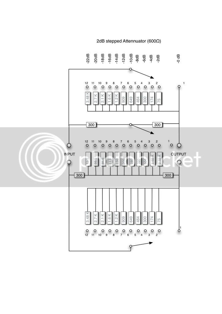
So the only way to do that is to do a low-Z pad after the transformer secondarys, you can use a stepped balanced constant 600 ohms pad with many stepps that is feed from the all three secondary windings configurated in series.
Or you can use a simple three stepped pad there you can switch between the three secondary windings and get 0, -6 and -9 dB attenuation.

--Bo

Thanks, Ben
 
It has been done & from what I hear works well.

A friend of mine (here on the Forums) told me about it but wasn't sure of the values. He recommended a -10dB U-PAD after the OT.
He mentioned the difference between the outboard (racked) & in console API pre's was about 10dB... the racked being hotter than the in console.
He said by adding the U-PAD, you can drive the amps more which makes for punchier drums & more character... I'm sure some of the color comes from driving the OT more as well.

Maybe he'll see this post & comment. :green:

I plan on trying this very soon.
 
[quote author="plumsolly"]Thanks kevin - Im just going to use the jlm circuit for 0, -10, -20db attenuation. By the way, here's a good page about pads for anyone that needs it: http://www.uneeda-audio.com/pads/
-Ben[/quote]

In that case I'd use the one on the right (the U-PAD) with the 470r in series.

Please post back your results... I'm curious about the -10 dB & your impressions.

PAD.gif
 
I know this thread has been dead for a while, but it seemed better to ask my question here than starting a new topic. The circuit suggested above by khstudio has the shunt resistor changing for each different attenuation. But from this site: http://www.uneeda-audio.com/pads/ I got the impression that RShunt effectivley sets the output impedance.

My question is, wouldn't it be better to keep Rshunt constant for each attenuation setting and have Rseries switching instead in order to keep the output impedance of the network constant for each setting? Or am I misunderstanding something?
 
brazilianwonderboy said:
I know this thread has been dead for a while, but it seemed better to ask my question here than starting a new topic. The circuit suggested above by khstudio has the shunt resistor changing for each different attenuation. But from this site: http://www.uneeda-audio.com/pads/ I got the impression that RShunt effectivley sets the output impedance.

My question is, wouldn't it be better to keep Rshunt constant for each attenuation setting and have Rseries switching instead in order to keep the output impedance of the network constant for each setting? Or am I misunderstanding something?
Sorry for the delay in responding: Yes, Rshunt does set the output impedance of an L/U-pad, but Rseries (combined with Rshunt) sets the input impedance- so switching either is a compromise. I ended up using a bridged-tee attenuator like this one
balancedbridged-tattenuator.jpg

I used only the values for 6, 12, and 18 db attenuation and a bypass. I used a 3X4 lorlin rotary switch. This circuit has a constant 600 ohm input and output impedance. If you wanted to, you could calculate a bridged tee pad for something like a 10k input and 600 ohm output to better approximate your existing impedance's. Use this for calculating those resistor values: www.odyseus.nildram.co.uk/RFMicrowave_Circuits_Files/Attenuator.pdf
As far as the sound, I did not get to experiment much. As soon as it was finished I loaned the preamps to a friend of mine and he liked them so much he's going to buy them. He leaves the attenuator on -18 db. Turning the gain up to compensate for that much attenuation does not cause crazy distortion - my friend records acoustic music. He has a 4312 that these stand up to quite well. My impression is that this is absolutely worth implementing. I hope this helps - don't hesitate with more questions. - Ben
 
drpat said:
You may have to experiment with your system depending on what level your tape deck is operating at and whatever Frankenstein API configuration your using.
absolutely - mine were very, very loosely "API"
-Ben
 
Thankyou all for the great replies. There is a lot of very handy advice there. I have a couple more questions though I'm afraid.

In the pdf that plumsolly linked to mentioned the equations you can use to calculate the resistor values. I got my calculator out and started plonking numbers in. Unfortunatley I ended up getting negative numbers coming out. A bit of head scratching and I realised that I need to have a higher dB level drop in order to get the values workable. (this useful little tool confirmed my suspicions: http://chemandy.com/calculators/matching-t-attenuator-calculator.htm).

This is a shame because I was hoping to go with drpats suggestion of a -10dB pad and at the same time incorporate plums idea of having Zin as 10K and Zout as 600, but I would need to have at least 19dB of attenuation in order to achieve that degree of impedance matching. My question is about what other people are doing in regards to Zin and Zout. Are you just using 600 for both values? If so, what audible effect do you think this has on the end product? obviously I'd like to get everything as matched as possible, but maybe this is not possible in the real world.
 
Back
Top