Passive Mastering EQ

GroupDIY Audio Forum

Help Support GroupDIY Audio Forum:

This site may earn a commission from merchant affiliate links, including eBay, Amazon, and others.
It is definitely not dead. I had a lead customer who was paying for the materials and driving the specification. I won't go into details but suffice to say that relationship has now ended and I have returned their money.

The good news is that during testing I realised the 10dB range version tries to satisfy too many (non mastering ) requirements which makes including some features difficult. So, bottom line is we are now back a few squares and resetting back to the 6dB version so basically it is 0.5dB steps all the way.

Now I have sent off the Gerbers for the first poor man's tube mixer PCB I might even have a little time to look at the mastering EQ.

Cheers

Ian
 
Hello Ian
any good news about this cool Eq project  ?
; )  … cheers

Ps :
I Iprefer soldering cable  connections from rotary switch selector and caps/inductors board ,
because very much better and "diyable" in case of rotary switch replacement ….
it take a bit more time in assembly ,
but so less in case of repair , and not new pcb required ,
…desoldering 12 or more rotary switch pins from a pcb sound like a bad "nightmare",
overall when very little "room" is available between pcb pads…. , very easy to broken them….
(..had so very bad experiences with Elma on Focusrite ..)
 
@R2D2

No news right now. I am very busy working on the poor man's tube mixer and the Mark 3 tube mixer. But I will ge around to this before long. A lot of it is done but skewed towards one particular clients needs. I just need to get it basically on track again.

I understand your point about about PCB mounted switches. However for the connections to LC components I prefer not to do it this way because of the increased stray capacitance and inductance. However, there is nothing to stop you wiring to the LC PCBs if you wish.

This design uses a single resistor string that is common to all the bands of the EQ. This means that all the level switches are connected together and I think this is more reliably achieved using a PCB. However, once again there is nothing to stop you making wired connections using rotary switches of your choice.

Cheers

Ian
 
ruffrecords said:
@R2D2

No news right now. I am very busy working on the……………………
……..your choice.

Cheers

Ian

thanks for reply Ian ,
only for curiosity…
this one is an old "version" ?
https://groupdiy.com/index.php?topic=65912.msg835039#msg835039
cheers
 
r2d2 said:
thanks for reply Ian ,
only for curiosity…
this one is an old "version" ?
https://groupdiy.com/index.php?topic=65912.msg835039#msg835039
cheers
That is a completely different design. It is essentially a cost reduced version of my original 3 band Pultec design. Both are now open source and you can download Gerber files to make your own PCBs here:

http://www.customtubeconsoles.com/diy

in the OpenSourcePCBs folder.

Cheers

Ian
 
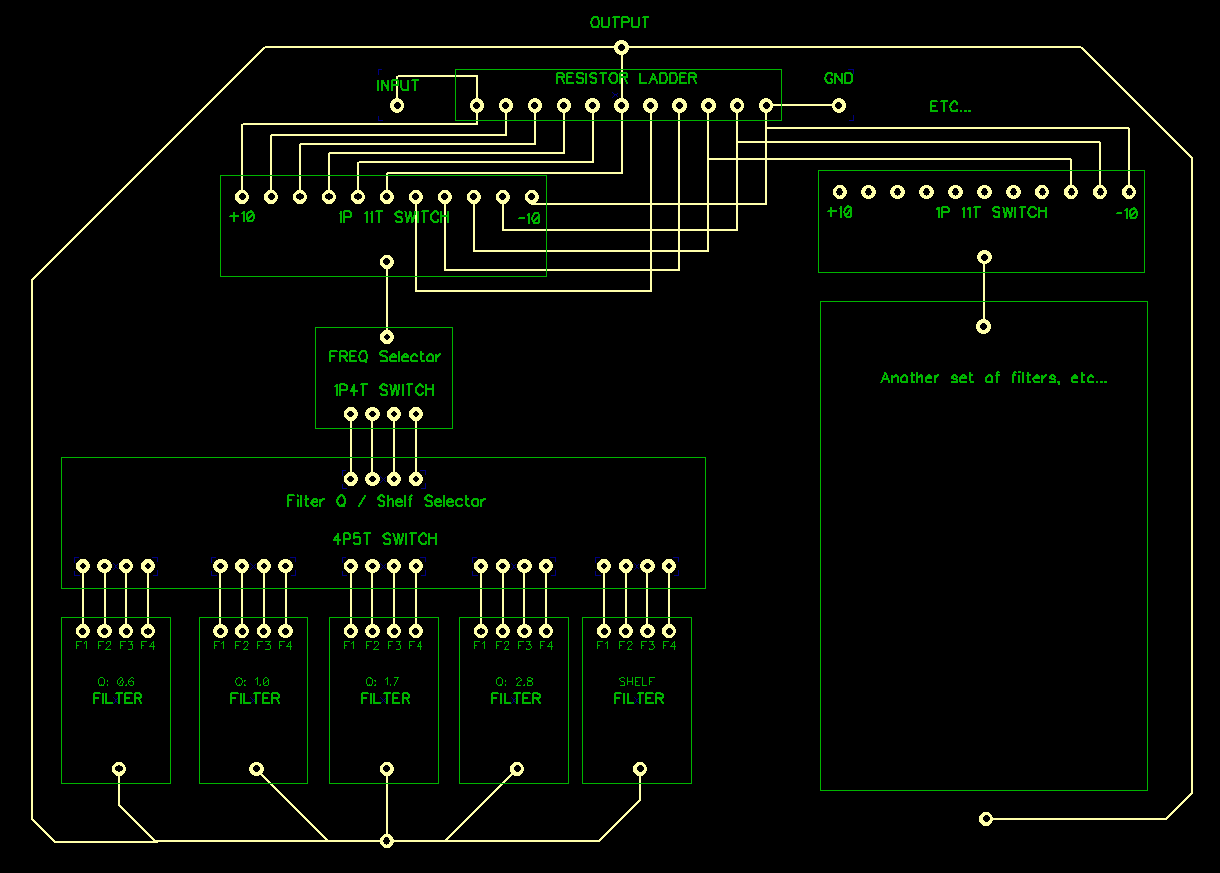
So I've been looking over the documentation as it is close to what I'd like to build. A slightly modified RS56

Basically bass will have selection for low shelf or one of the 4 Q filters, midrange will just have the 4 Qs, and treble will have high shelf or one of the 4 Qs

I wanted to make sure I was grasping the concept of the shared resistor ladder in your paper and also switching between different Q filters or a shelf filter, etc...

I couldn't really come up with a good way to visualize what I'm talking about so I used PCB layout software to make an example - Hope this makes sense!

lmU4cNJ.png


You got the the common resistor ladder and its wiring to the switches for each band spot on.

One 'property' of this EQ when configured for +- 10dB range is that the boost Q is considerably less than the cut Q. This is because the characteristic resistance (which determines Q) is much lower in the cut section because all the resistor values are lower. The change to a10dB boost/cut range was made by the customer. The original mastering EQ design was +-6dB, which was thought to be plenty for mastering purposes, and also has the advantage that the boost and cut Qs are identical.

Note also that lowering the Q by inserting a series resistor will reduce the maximum available boost/cut. If you want to retain the full boost/cut range and vary the Q you need separate LC pairs for each Q at each frequency which I think is what you have indicated on your schematic.

I like the way you have drawn the schematic. Novel yet perfectly readable.

Cheers

Ian
 
Perfect, thank you!

You got it right,  it is showing a separate LC filter for each Q.

With +- 10db how different is the cut Q? Is it a major difference (Like going from super sharp to super broad, or vise versa?) or just changing a little sharper or broader?

I also have a few questions on the LC and Shelf formulas.

The xls math file you posted for 6db filter calculation - is it possible to use that to calculate for 10db filter as well, or is there a formula change needed? ( I noticed the EQ Impedance is different than the "Characteristic Impedance")

Example: for a 32k pot (which I assume is the resistor ladder) and a Q of 0.6 -  MIN/MAX is 6400/8000  - and a frequency of 1k
L=0.511

To use the formula (L = (Q*Rch)/(2*PI*f)) Rch is 5344 to get that same L value.

Does this mean that changing from 6db to 10db, but changing nothing else - there is a change in the impedance of the circuit?

I also didn't see C or R calculations in your paper so I'm unsure how those are calculated except by looking at the excel formula but I don't know how that relates to pot value and/or impedance or if they change with 6db vs 10db resistor ladder

I'm still learning!

edit as I did a lot more of the math:

So looking through all the calculations I was able to derive the following:
C = Capacitance in picofarads
L = Inductance in Henries
R = Resistance in Ohms
Rch = Characteristic Impedance in Ohms
f = Frequency in Hz
PotK = Pot in KOhms

Characteristic Impedance:
Rch = 167*PotK

Most of the rest derive from this, so I assume this is the main formula that would change?

Bell Filter:
L = (Q*Rch)/(2*PI*f)
C=1000000000/(39.478*L*f*f) (where did 39.478 come from?)
R=1000*PotK/50

High Shelf :
C =1000000000 / (2*PI*Rch*f)

Low Shelf:
L= Rch/(2*PI*f)

Based on the above (hopefully I'm accurate), which would change for switching from 6db to 10db - I assume the calc for Rch would change then everything else should fall into place except maybe C in the bell filter as I don't know where 39.478 came from? Would R calc in the bell filter change?
 
With a 10dB EQ, the cut is sharper than the boost. In the REDD EQ mid boost/cut for example, the nominal insertion loss is about 14dB. The extra above the required 10dB allows you to adjust the resistor ladder to compensate for the driving source impedance and the series resistance if the inductors.

The pot divider is essentially 20K and 5K to give a nominal attenuation of 14dB. This means the characteristic resistance of the cut is one quarter that of the boost.  Since Q = 2 x PI x f  x L /  R where R is the characteristic impedance, the Q of the cut is four times that of the boost.

For 10dB you need a potential divider ration of at least 2.16:1 even with a zero driving source impedance and perfect inductors so the cut Q will always be at least twice the boost Q.

If you use the 6dB version, both halves of the attenuator are the same so the Q is the same for boost as for cut.

To calculate L and C then, knowing the desired Q and the actual characteristic resistance calculate L from the above formula, which rearranged is:

L = (Q x R)/ (2 x PI x f)

The calculate c from f  =  2 x PI x square root( L x C)
Squaring both sides gives:

f^2 = 4 x PI^2 L x C

39.478 is 4 x PI^2

The characteristic resistance depends largely but not entirely on the top and bottom resistance of the ladder network. Rather than calculate it I simulate it with a single inductor and capacitor, measure the simulated Q and then derive the characteristic impedance from the result.

Cheers

Ian
 
Ahh ok, I get it - C=1000000/(4*PI^2)*F^2*L

I think I'm getting the Q problem too. A 6db ladder has symmetrical Rtop and Rbottom at 0db, while the 10db ladder is asymmetrical, with Rtop a bit over 2x RBottom, hence the Q doubling at cut. Interesting.

I did check the software version of the RS56 and the cut is a lot narrower than the boost on the emulation, so I assume that is exactly what was going on there.

I think I should be able to duplicate the RS56 pretty decently with what I've learned. Ordering some parts to breadboard a portion of it to test. Thank you so much for your help!
 
In practice, a sharper cut can be an advantage. Cut is most often used to remove some small unwanted band of frequencies without adversely affecting the overall sound. The Classic Helios 69 EQ designed by Dick Swettenham (ex Abbey Road) has a 4 to 1 top to bottom ratio so the cuts are very noticeably sharper. I an not certain but I think the Pultec MEQ5 is similar.

Cheers

Ian
 
Greetings from the future. I stumbled across this thread recently and having read it from start to finish, my interest is very much piqued.

Ian, I think it’s fantastic that you’ve been developing this with input from the community. I know you’re busy focussing on other projects but I’m interested to know if this still planned to be developed further?
 
Yes, I do plan to release it into the wild in the future. The bulk of the development work is done and I have already used the same basic design to build a custom mastering EQ for customer.

The basic plus or minus 6dB topology has some interesting properties. Apart from the range being more than adequate for mastering purposes it also has the same Q for cut as for boost.

Its most obvious disadvantage is that overlapping EQ bands do not sum. The maximum boost or cut is 6dB. However, if you limit the boost cut range to 3dB of the 6dB, the overlapping ranges will add. This may or may not be useful.

The other thing that has changed is the original design had all the EQ level switches on a single PCB along ith the common resistor ladder. This avoids a lot of complex wiring between switches. However, it does mean you have to decide the number of bands in advance. For the custom version I mentioned above I developed a ribbon cable system that allowed a quite large number of bands. They were also stereo.

So bottom line is, it works, there is some interesting potential but I need to find time to do it.

Cheers

IAn
 
Cool, thanks for the update.

Its most obvious disadvantage is that overlapping EQ bands do not sum. The maximum boost or cut is 6dB.

So if my understanding of passive filters is correct, this is because they can only let through what was already there before the input signal level was reduced.

For the custom version I mentioned above I developed a ribbon cable system that allowed a quite large number of bands.

I recall earlier in the thread you were concerned about stray capacitance here. Sounds like that isn’t an issue, which is good news - a custom number of bands is no bad thing imo.

I’ll be following progress with interest!
 
Cool, thanks for the update.


So if my understanding of passive filters is correct, this is because they can only let through what was already there before the input signal level was reduced.
Exactly
I recall earlier in the thread you were concerned about stray capacitance here. Sounds like that isn’t an issue, which is good news - a custom number of bands is no bad thing imo.
The reason stray capacitance is much less of an issue is because I changed the impedance of the EQ from 10K to 600 ohms. This means you either need to drive it from a source capable of driving 600 ohms or buffer the EQ with a low output impedance buffer - I used a THAT1206.

Edit: it also means use can use much smaller value inductors which is great for bass sections. Conversely it does mean capacitor values become proportionally larger but that is not an issue as they only need to be 50V rated so there are plenty of film ones to choose from.

Cheers

Ian
 
Back
Top