Peavey Poweramp Resonance & Presence Modification - Weird Behavior With Low Resonance Settings

GroupDIY Audio Forum

Help Support GroupDIY Audio Forum:

This site may earn a commission from merchant affiliate links, including eBay, Amazon, and others.

Lumberjack

Member
Joined
Jun 17, 2024
Messages
22
Location
Europe
I own a Peavey Classic Series 120 mono poweramp that doesn't have any resonance or presence controls. There is a stereo version of this poweramp, the classic series 120/120, which does have resonance and presence along with input level on the front instead of the back. If you've never heard of this poweramp, think of it as the predecessor to the 5150 poweramp.

I assumed that the two circuits are identical, one just being two mono blocks in parallel, and I thought that I could just insert the presence/resonance circuit 1:1 into my own mono poweramp, but after inserting the little circuit into the poweramp, I noticed that the resonance control acts very weird when set to the lowest 20% or so of the potentiometer range. There's no sound and the powertubes seem to be overwhelmed as they start to overheat drastically.

How is this possible? Why doesn't the stereo version of the circuit work in the mono version when the two designs are 99% the same. There are some differences near the diode bridge, like added capacitors, different values etc., but that's not the EQ circuit anyway and shouldn't influence the behavior of the resonance control.

In order to better understand what I did and what the circuit looks like, here are some schematics:

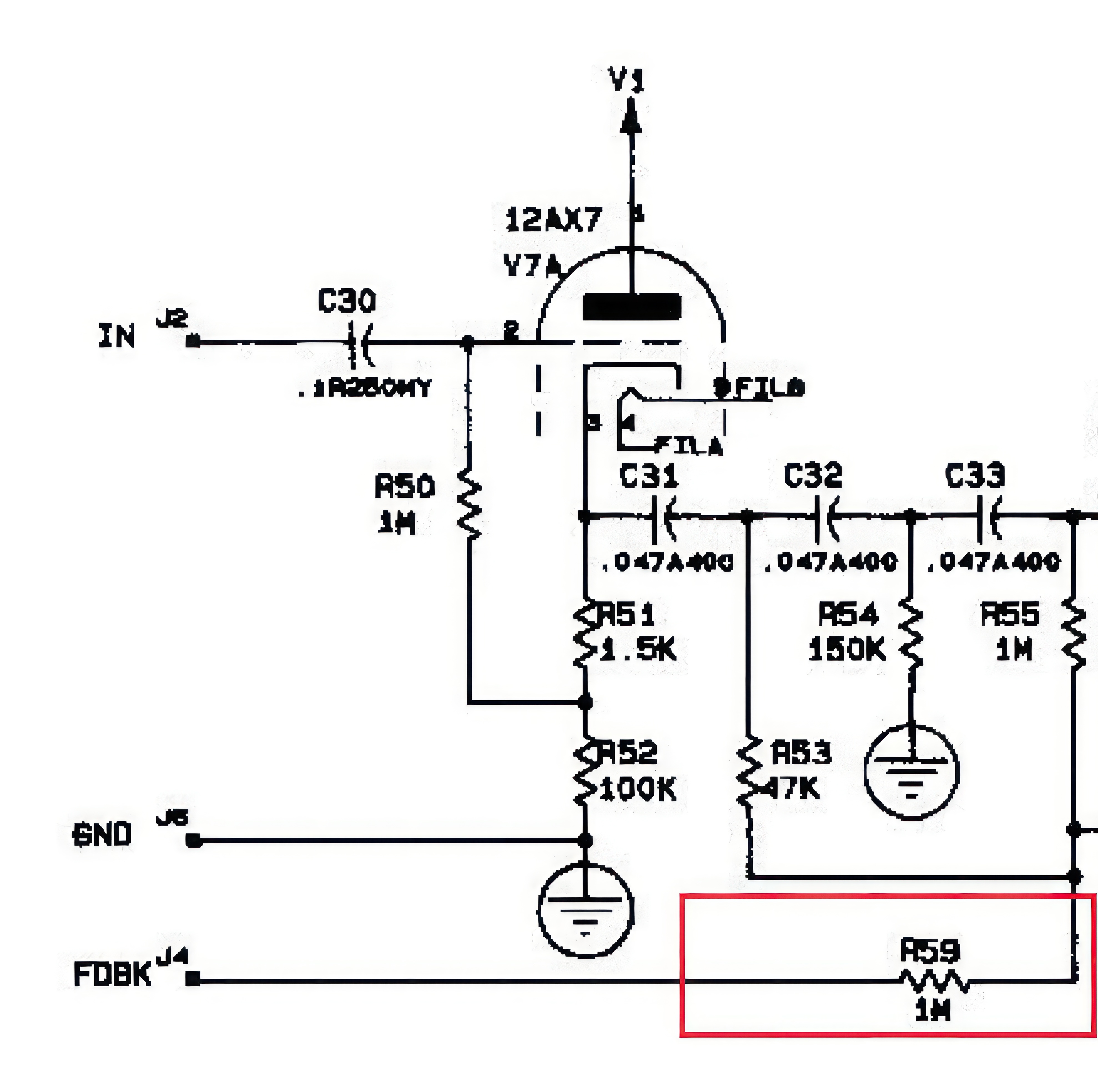
Mono version input stage without presence/resonance circuit, instead there's only a 1 Megaohm resistor which is replaced by the presence/resonance circuit:
A1j3Rty.jpeg


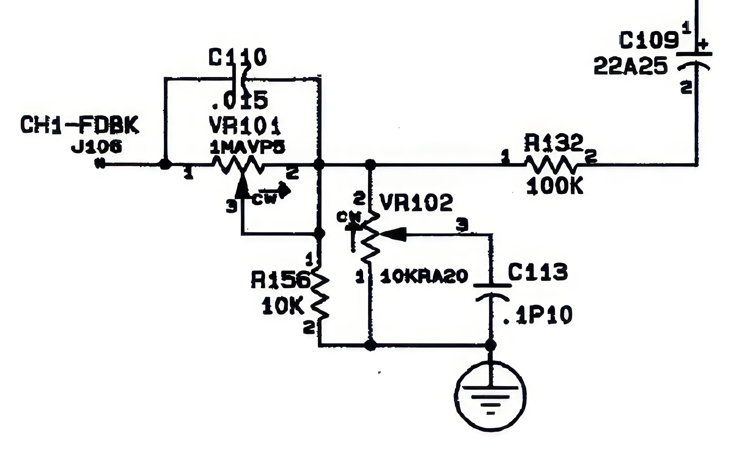
Here's the presence/resonance circuit taken directly from the stereo version:
AJ66Crx.jpeg


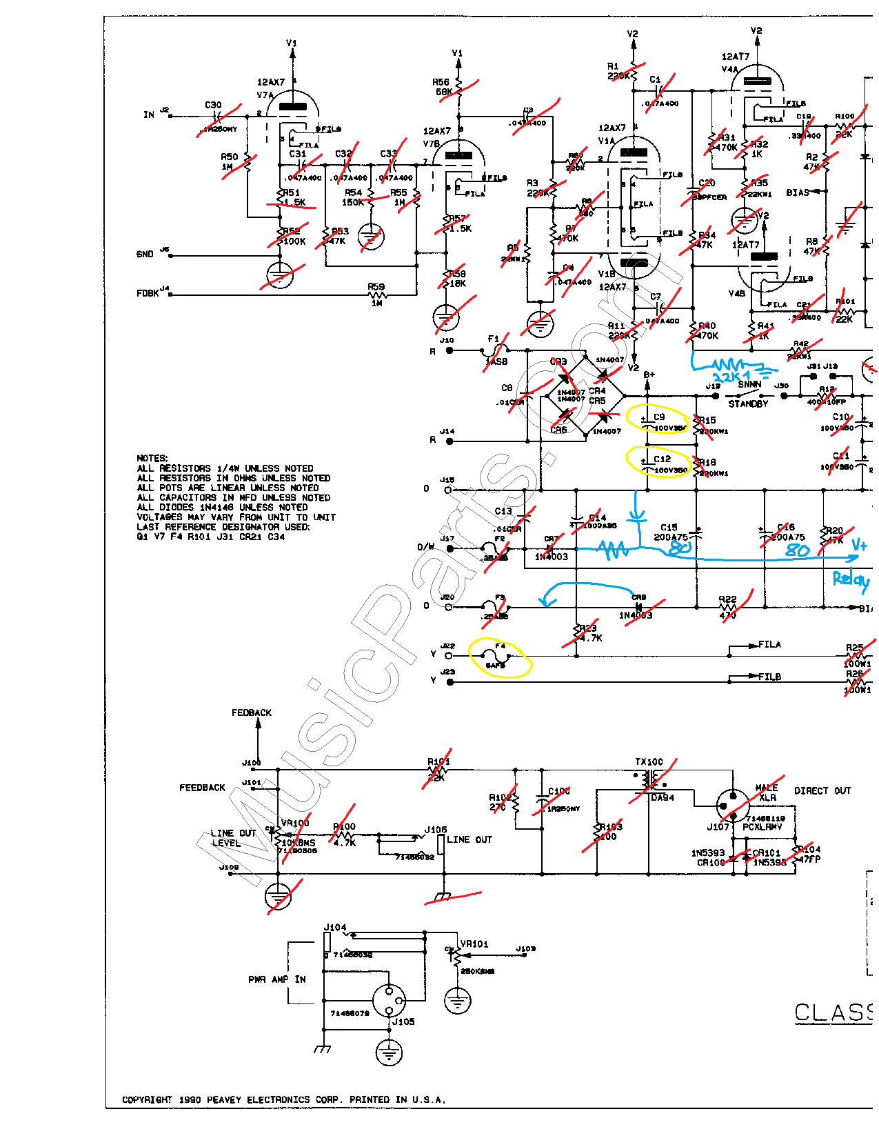
And here's the full mon version schematic which I've compared to the stereo version schematic. Crossed out elements in red are identical between the two versions, blue/yellow denotes either a different component value or additional/omitted components. It has two pages and the first one overlaps quite a bit into the second one, which is why I've outlined it in green on the second page:
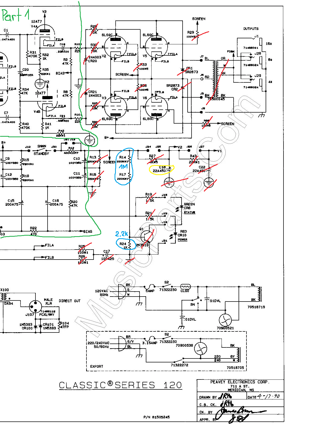
3omxpKz.png


GBozSy7.png


Here's also the PDF version of the stereo poweramp:

https://pdfupload.io/docs/3eba0f65

Are the component values purposely false in order to protect the design or should these values theoretically work anyway? Why is it so behaving so weirdly when the resonance potentiometer is below 20% of its range? It's behaving downright dangerously and I really don't know why a circuit that works in unit and doesn't work in the other even though the schematics are extremely similar.
 
To much NFB or NFB of the wrong phase can cause an amp to oscillate ,
Usually amps take feedback from output transformer secondary back to the phase invertor to form a presence control .
In this case the NFB loop encompases the entire circuit appart from the first stage , that requires the correct compensation components otherwise it can very easily become unstable .
Component placement and even the routing of the FB wire through the chassis can also cause unwanted interactions .

Maybe take a very close look at the wiring of the amp w/ resonance and presence and try and closely copy that layout .

If your getting the desired effect over most of the range of the controls and only at extreme setting things fall appart you need to find a way to reduce or limit the overall FB level , you could try sourcing the FB from the 4 ohm winding instead of the 8 ohm , you could also try increasing the value of R132 .

Once the sun comes up on the western seaboard USA , CJ might chime in , he'd probably know .
 
In the stereo amp R126 which is the lower cathode resistor on the second stage is 22k ,
On the mono version R58 is 10k , might be worth swapping it out for 22k to see what happens .

Maybe a closer re-check of component values especially the coupling and NFB network capacitors , a wrong value in these positions can easily cause instabillity .
 
Last edited:
In the stereo amp R126 which is the lower cathode resistor on the second stage is 22k ,
On the mono version R58 is 10k , might be worth swapping it out for 22k to see what happens .

Maybe a closer re-check of component values especially the coupling and NFB network capacitors , a wrong value in these positions can easily cause instabillity .
Thank you for your answers! I made a mistake crossing out the R58 as it really is different compared to the mono version. Maybe changing it would yield a better result, certainly worth trying.

The parts list for the resonance/presence circuit is fairly simple and there's also a parts list at the end of the stereo version PDF. Here are all the parts values:

Capacitors:

C109: 22A25 = 22 MFD 25 VDC LYT CAP

C110: .015 = 0.015 MFD 10% 50V

C113: .1P10 = .1 MFD 50 VDC 10%

Resistors:

R132: 100K 1/4W 5%

R156: 10K 1/4W 5%

Potentiometers:

VR101: 1MAVP5 = 1 MEG AUD VPC 5% TAPER

VR102: 10KRA20 = 10KRA MIN 20% TAPER

I'm using the correct specifications on all parts, maybe it's the tighter tolerance of the VR101 (resonance) pot of 5% that I'm overstepping by a bit...

What about the Output Transformer wiring differences between the two versions? It does look a little bit different on the stereo compared to the mono version. Maybe that's the cause of the issue?
 
Last edited:
I am not a tube guy but recall Peavey's efforts in resonance/presence like amplifier sound shaping. I was more familiar with these efforts associated with solid state amps to mimic vacuum tube amplifier's relatively higher output impedance and interaction with loads.

To increase the output impedance of an amplifier involves "positive" feedback, something that can easily get out of hand if applied carelessly.

I recognize James Brown's and Jack Sondermeyer's (RIP) signatures on that schematic. James was the lead engineer over many of Peavey's popular tube guitar amps (including 5150).

Sorry I have no specific advice but expect the use of positive feedback to be well controlled and modest.

JR
 
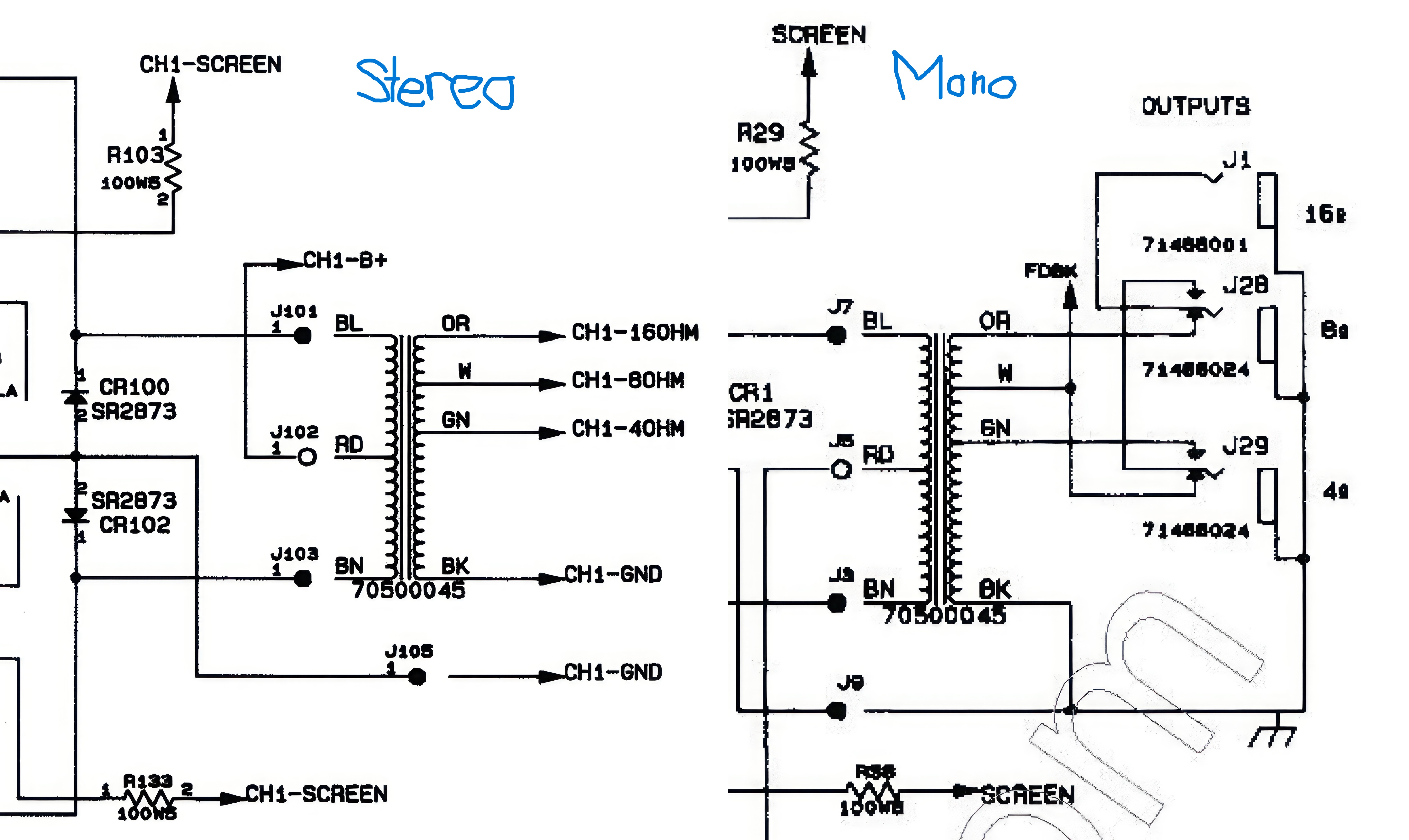
A quick update: I found that there are differences in wiring between the output sections of the OT between the mono and stereo version:

0Hj8Zz1.jpeg


The mono version hasa distinct "FDBK" line ranging from the 4 ohm tap to the white cable of the OT. The stereo version OT section has no such "FDBK" line.

Both the mono and stereo version have a connection to an FDBK line, but in the stereo case, I don't see where that is exactly.

There's also no grounding on the ohm taps in the stereo version compared to the mono version...

Could this be the root problem behind the hot power tubes and oscillations?
 
Both the mono and stereo version have a connection to an FDBK line, but in the stereo case, I don't see where that is exactly.
This amp has additional circuitry for the "mono/stereo" switch which is missing from the schematic. There must be something taking the two sides and combining them, and this is likely where the FDBK node is being tapped from.

If you look closely on page 4 of your PDF, the entire left side of the schematic is missing, along the sides you can see the CH1-16 ohm and CH2-16 ohm labels, so this missing part is likely where the feedback signal is coming from.
 
If you look at this Classic 50/50 PDF, it shows a similar mono/stereo topology, and the schematic is complete, and it shows you how the feedback signals are generated.

https://music-electronics-forum.com/filedata/fetch?id=857190&d=1705861414
So in other words, there's much more to this than using that simple resonance/presence circuit up front. Probably much more complicated to assimilate the back-end to the stereo version so that the mod doesn't make any sense at this point...
 
Not at all: I just think more investigation is needed.

The symptoms sound like ultrasonic oscillation, but you really need a scope to see this properly and to verify that you fixed it.
 
Not at all: I just think more investigation is needed.

The symptoms sound like ultrasonic oscillation, but you really need a scope to see this properly and to verify that you fixed it.
This whole switching circuit between mono/stereo is a bit too complex for me to understand. I'd appreciate it if someone could point out how exactly I should modify the circuit of the mono 120 version so that it works with the resonance/presence circuit up front. I'd even pay for that information, just PM me if you can provide a detailed part of the schematic that I should implement.
 
None of the switching is needed, and it looks like you've connected the circuit in the same manner.

What test tools to you have to debug the issue? Which tap from the OPT are you taking the feedback signal from? Are you sure it's the correct phase?
 
None of the switching is needed, and it looks like you've connected the circuit in the same manner.

What test tools to you have to debug the issue? Which tap from the OPT are you taking the feedback signal from? Are you sure it's the correct phase?
I really don't know if it's the correct phase and I don't have an oscilloscope either.

The mono 120 poweramp that I have is all stock except for the little resonance/presence circuit that I want to insert in place of the single 1M resistor that is usually connected to the feedback loop. Everythign else, inlcuding the transformer section, is wired exactly as it's displayed in the mono 120 schematic

I'm just very unsure what to do with the feedback loop section of the stereo poweramp and what this exactly implies for the mono version if I indeed wanto to use the presence and resonance circuits from the stereo version.
 
Last edited:
Can you describe what happens as you pass from the resonance control fully 100% and then cross through the 20% threshold? The the sound cut out suddenly (e.g. it goes from full volume to zero instantly)?

Without test tools you will be poking blind at the issue, and will be left to shotgunning parts to see if the behavior changes.

If I had to recommend a change blind, I would increase the feedback series resistor in order to reduce the amount of NFB. It's the 100K R132. Try a 220K. You didn't answer which tap you are using for the feedback signal (16 ohm, 8 ohm, or 4 ohm), but if you are using the 8 ohm like the stereo version, you can try moving it down to the 4 ohm which reduces feedback as well.
Yes, the tone dwindles and finally disappears abrutly and the power tubes get overheated and recently, after trying a higher value for R132 (500k) the resonance potentiometer caught fire.

Maybe I'm misinterpreting the schematics, but the side-by-side picture of the mono and the stereo version OT sections shows that the mono version, which I have in its original form without any mods, has the FDBK line connected to the white cable and the 4 ohm output jack. Or am I misinterpreting it?

The mono poweramp that I have has no modifications, what is seen in the schematic is what's actually in the poweramp, no modifications. The only modification is the resonance/presence circuit, but it's on a little board apart from the pcb board.
 
If the power tubes are overheating, it could be for a number of causes, including bad tubes, low frequency oscillation swamping the bias circuit, and an unsuitable feedback setup.
You need a scope to understand and troubleshoot this. You can get cheap ones on Amazon.
 
If the power tubes are overheating, it could be for a number of causes, including bad tubes, low frequency oscillation swamping the bias circuit, and an unsuitable feedback setup.
You need a scope to understand and troubleshoot this. You can get cheap ones on Amazon.
Yes, I figured it probably has to do with low frequency oscillation since the problem only occurs on the resonance knob and not the presence knob.

I think the main difference is the OT wiring and the whole output jack section. I found a complete Classic Series 120/120 stereo schematic and there's now a part that describes the "FDBK" line that was otherwise missing from the first PDF of the stere version that I shared.

Here's the complete PDF:

https://pdfupload.io/docs/21d64b0d

There's no FDBK line directly near the OT of the stereo version and the stereo version also utilizes another resistor (R310 first page PDF above) but I'm not sure that that little 47k resistor could make the difference, it's probably got more to do with the rest of the wiring.

Can somebody tell me how exactly I can translate the stereo OT section so that it works for the mono version, maybe point it out in the schematics?

The mono schematic is fully posted in my original post.
 

Latest posts

Back
Top