Phantom pwr from a DC to DC converter?

GroupDIY Audio Forum

Help Support GroupDIY Audio Forum:

This site may earn a commission from merchant affiliate links, including eBay, Amazon, and others.
very interesting design Bo, however PRR might not be happy about the inductor present once again but I like it!

built by sophisticated guys like you

:shock: I appreciate the comment but I don't consider myself even close to being sophisticated or even that good. I just try to make my designs work as best as I can with help from others like yourself whom are more knowledgeable than I will be for a long time.

the diode/cap ladder can be made quieter but you will run into the $$ issue once again.

555 wiggle frequency
:green: Yeah they do tend to jitter and oscillate strangely and sometimes completely random from IC to IC. If there were a way to time them in a way that doesn't use an R/C circuit then we might get rid of that completely.

I'm guessing the voltage multiplier uses the same diodes that the input rectifier uses?

design the preamp for 48v is one of those "why hasn't anyone done this yet" questions that no one can answer but no one really has the initiative to do either. It makes total sense though.
 
http://www.onsemi.com/pub/Collateral/MC34063A-D.PDF

i'm looking at these.. pretty much the most simple design i can find.


I have done the math for 12v in/48v [email protected] if anyone is interested. I might order a few of these with some other parts and give them a try.

you are looking at 170uH L .. around 38 turns of 22AWG wire on a small ferrite core.

EDIT:

http://www.onsemi.com/pub/Collateral/AN920-D.PDF
 
Got some information for the Sony DC/DC convertor mentioned above via a UK SOny service center.
Price for 50 pieces would be around 33 USD/each.
Seems to be a reasonable , or not ?

That's shipping from Japan to my place (Belgium)
Dunno about customs
 
I've been kicking this idea around for a while, I think it could really help people simplify their DIY preamp module racking projects. The power supply I build has a good 48V supply in it, but there are plenty of times when a simpler, cheaper PSU wold be great if it weren't for the phantom power requirement.
As far as I'm concerned, the device would need to run off of anywhere from 12 to 28V DC, produce a well-regulated 44-52V output capable of delivering 50mA (10mA for each of two indicator LEDs plus 14mA into each of two channels) without complaining, be about the size of a 2520 amplifier, operate at 1MHz or higher, and cost less than $20 to build.
Anything more than 2 channels' worth and you're going to be better off with an actual 48V power supply. The 1MHz clock speed should be very doable with modern components, whether it be a new National chip intended for cell phone backlights, or a discrete circuit with high-speed switching diodes. The high frequency will make the inductors and capacitors small (and cheap) and will make shielding the circuit much much easier.
 
Most of those darn converters take a dc voltage and make it smaller. 5 volts seems to be the most common.
15 volts is the highest I have seen. Anything that puts out 48 is probably gonna be noisy.
I say spend the 5 bucks on a transformer. Clean and reliable.
'
 
Assuming it was not noisy I'd be down for buying one of ulysses' converters. It sounds very useful to me as a product and learning experience.
 
The LM500-6 from National Semiconductor would be a pretty good choice, I think. It's small and requires relatively few external components. It can be made to run at 1.3MHz which will be great for keeping it small and quiet. There's actually a schematic in the data sheet for a 48V output coming from an 18-36V input. I haven't read the whole sheet yet, but I'm sure it will be relatively easy to modify it to take a 10-30V input (12V-28V with a bit of wiggle room). I also think it could be made to put out a few extra volts to make room for a linear regulator at its output, for those of you who still don't trust switching supplies near your audio.
http://cache.national.com/ds/LM/LM5000.pdf
 
ok, I think people are starting to misunderstand how DC-DC converters work and that there are differences in the way they work.

there are a few different kinds:

boost
buck
boost-buck
Cuk
flyback

and a few more that are more exotic.

one of the main things that differs between them is where the inductor and switching device are in relation to each other in the current flow.

Boosts do as they say, they output a higher potential than the input at the cost of current drive. the inductor is in series before the switch to ground.

bucks are step downs. the switch is in series before the inductor in series.

boostbucks can be either higher or lower potential but are more efficient than the others. the switch is before the inductor to ground.

Cuks are based on capacitive energy transfer not inductor, but they still use inductors which are in series with the switch to ground.

flybacks use a transformer instead of an inductor, therefor can have much higher power densities. they are also grouped with forward converters.

there is much more to go into like discontinuous/continuous mode and other such things but i'll get into that later.

Back to what i was getting at, a simplified look at a boost converter.

a simple boost converter will magically turn your 12v into 48v easily using the basis of a failing field in an inductor vs. capacitance. switching your switch device to ground causes the inductor's current to rise at a linear-ish rate feeding through your diode, then switching the switch off causes the voltage to rise feeding through your diode. doing this at a preset duty cycle gives you a specific voltage. you now have to smooth this with ripple caps just like any other powersupply but at the very least switching powersupplies have one obvious advantage. yup that is that the ripple will be of a known value and you can easily design your smoothing bits to give you clean DC.

I think a simple boost converter would be ideal here and likely be under 10$ to build and might spark some interest in the future.. the future is switching powersupplies!

If i missed anything I'm sorry I'm exhausted.
 
check out the national lm5000 series. just a few caps, an inductor and diode. Fet is internal.

sorry I beat you to it Ulysses! check page 1 of the thread! :green:

but yes the lm5000 is a decent choice however I'm not so sure that switching close to tv/radio type frequencies is all that good. at such higher freqs signals tend to penetrate a little more. i think that 100khz and somewhat above would be fine. current density isn't an issue and neither is the noise from high currents so I don't think switching that high would make a real difference besides, you are really looking at saving a few cents at the most as the inductors with such small cores are not only cheap but plentiful. In fact I think we could likely find some in junked switching PSUs for some real DIY action.
 
There's more to consider than just switching frequency. Like the mode of control. Is it PWM or variable frequency? Hysteretic? Note the feedback control loop is right in the audio band. Having a switching frequency of 1MHz or some other high number guarantees nothing. You have to design the control loop for minial impact to audio.

Other aspects that help are using proper ferrite core inductors or transformers. With shielding. Winding your own will likely lead to a lot of magnetic spray (to other circuits).

Of course it can be done, and wouldn't cost too much. But it takes more than what you see in a typical dc-dc application note. Extra filtering on both input and output will help. You could even do a hybrid: dc-dc step-up folowed by a linear regulator.

Actually, there are quite a lot of choices. Maybe even one of those new LED backlight drivers for cell phones. Could be perfect. Except maybe they're current controlled. Sorry, just thinking out loud.

jh
 
I did some tests with a Traco dc/dc converter a year ago and it worked fine on the bench!
I used a 24V in, +/-15V out 1W, as the converter is in/out's are isolated from each other I just added the 30v to the 24 and got 54v out.

Here's a drawing http://www.vintagedesign.se/schematics/24v%20to%2060v.pdf

Don't know how clean it is!
 
There's more to consider than just switching frequency. Like the mode of control. Is it PWM or variable frequency? Hysteretic? Note the feedback control loop is right in the audio band. Having a switching frequency of 1MHz or some other high number guarantees nothing. You have to design the control loop for minial impact to audio.

yes true. Most modern DC-DC converters are now PWM driven though. Not all designs need feedback at all. a normal PWM output can be tuned to give the desired voltage/current without regard to actual load up to the point of pulling the whole system down but I'm not sure where you see that the feedback is in the audio band, the feedback is generally current sense via resistor drop, essensially sensing voltage level, not frequency. If the output is filtered enough then there should be no ripple on the feedback at all, but if there is then you might get a type of oscillation.

Other aspects that help are using proper ferrite core inductors or transformers. With shielding. Winding your own will likely lead to a lot of magnetic spray (to other circuits).

very true, this is why computer PSUs are in their own cases separate from the motherboard components.. BUT if you have enough distance(deemed by the switching freq, mag field and other such things) then you can be unshielded. computer powersupplies are also operating under huge loads and power densities. we are talking about less than 200ma here. ferrite cores were mentioned in an earlier post of mine in this thread.

Of course it can be done, and wouldn't cost too much. But it takes more than what you see in a typical dc-dc application note. Extra filtering on both input and output will help. You could even do a hybrid: dc-dc step-up folowed by a linear regulator.

this would be a cheap AND easy solution. App notes/datasheets are for the circuit in question, not supporting circuitry usually. so yes you are correct in stating that there is more to it, but this *should* be obvious to those interested even though it seems like it's more complicated. to me it's almost a matter of understanding what you are getting into. I could read anatomy books all day long and understand what they say but does that make me think i can go do surgery? nope. but on the other hand, we could easily overdo the situation with excessive design. do we really need all those extra Ls, Cs, and Rs on the input and output? likely not. In DIY this is not much concern, but in the real world this is cost and possible failure modes.

People seem to assume that because it's switching that there will be noise on the output for some reason. well yes there will be noise on a improper design but if you follow the data and do a little O'scoping you can make a switcher output like a linear reg and save some heat too.

we have to think about what's happening in the world too.. china has produced a billion different types of switchers and a lot of them are crap. this has flooded the market with noisy, poorly efficient, poorly regulating powersupplies that are fine for digital devices, but really suck for anything analog. this has given switchers a bad name and the stigma seems to have stuck very well even for those who understand the technology and especially for those who don't.

I'll get some ICs and drop a small board and see what I get in real life testing, but it might take me a few weeks to get it together with my schedule.

:thumb:

PS: thanks for the discussion!
 
[quote author="Svart"]sorry I beat you to it Ulysses! but yes the lm5000 is a decent choice however I'm not so sure that switching close to tv/radio type frequencies is all that good. at such higher freqs signals tend to penetrate a little more. [/quote]

National Semiconductor seems to agree with us as well. That's the part their website recommends when you punch in the parameters I laid out.

Higher frequency stuff can actually be shielded much more effectively - a thin copper shield can do more at 1MHz than Mu-Metal can do at 60Hz. Of course this assumes good clean grounding and layout. But the reason I would go for the higher frequency isn't really due to noise issues (which can be designed away) or cost (which is going to be modest regardless of the design). The biggest reason for me is that going with a higher frequency will make the caps and inductors physically smaller, allowing for a smaller circuitboard and a smaller total package. My idea is that this board could be about the size of a 2510 amplifier, and stuck inside of a shielded can. I imagine it would have four or five pins, maybe six. The remote shutdown option would be very cool because you could turn it on and off with a very cheap switch that doesn't need to be rated for 48V.
 
Hi guys,

Today I made a small DC_DC converter using the LM2577.
It's placed on a piece of shielding FE-plate, dimensions ca 2"x1.5" (from some old VGA monitors). All parts except the IC are also salvaged from the old monitors and switching PSUs. The IC costs cca 5 Euro in my local store.
The converter works very well. It produces stable output voltage (50V) from any input voltage between 8 and 25V (maximum on my bench PS) with very high efficiency and small ripple.
Ripple (spikes, more precisely) are 5mV without load and ca 15mV on 1k load (50mA), which is eliminated with an additional 100ohm/10uF network on the microphone input. I checked the PS on my (phantom power very sensitive) Sennheiser MKH-??? P48. It works equally well with this PS as with the console's internal PS (without any audio residues). Switching frequency is around 50kHz. I didn't find any substantial EMI from the converter.

Schematic and the design can be looked up at
http://www.moxtone.com/ostalo.htm

I just thought some people might find this helpful.

Regards,
Milan
 
That looks nice and simple. Reading through the data sheet, it looks like you could really improve the performance (get rid of those 5mV spikes!) by optimizing your component values a bit. Using ballpark figures, I guesstimate that you need a much bigger inductor (1500uH or so), a smaller Rc (compensation resistor) under 1k ohms; a bigger Cc (compensation capacitor) up around 1.5uF, and a lot more input capacitance. These values all depend on your minimum input voltage, your output voltage, and your load current. By planning for a minimum input voltage of at least 10 or 12V, you make things a bit easier by reducing the max duty cycle. Likewise, planning for a max load current of 50mA helps too. The formulas in the data sheets are pretty straightforward. Unortunately, the size of the inductor is going to prevent this circuit from being very small or very cheap.
 
get rid of those 5mV spikes!

Yes, easy to do. Don't play with the inductor by making it too big. There is only so far you can take the basic circuit. It is already pretty much optimized. The trick is to add another filter section on the output. Put it after the feedback, so it doesn't become part of the loop.

Basically, add a ferrite bead into a tantalum capacitor (or organic electrolytic like a black gate). This forms a simple RC low pass filter at the higher frequencies, and acts like a dead short at low frequencies.

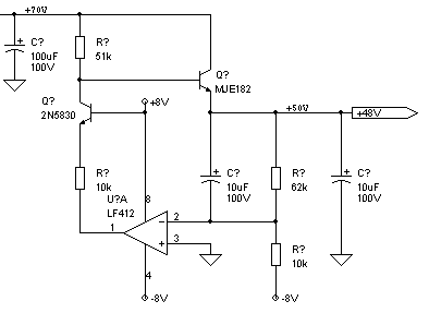
As mentioned previously, the other option is to go hybrid and add a linear regulator. Here's the one I came up with for a project in the works (but uses +/-8V supplies in addition to the +70V input):

phantom.gif


jh
 
> output of 39VDC. In that article he tested several mics including an AKG414 and they worked at that voltage.

It better. It is rated to work down to 9V. I fed mine 27V for years.

Internally, the 414 regulates to about 8V, so feeding it more voltage just makes heat (obviously not a problem).

There are about 3 classes of Phantom mikes:

* early ones used the Phantom as capsule bias as well as buffer power. These never need even 2mA but always need to be fairly close to 48V to give rated sensitivity. Unfortunately, several recent low-price mikes also use Phantom for bias, apparently including my new "free" MXL 990. Running these mikes on 24V power will reduce sensitivity at least 6dB.

* most modern "good" mikes do like the 414: they regulate whatever Phantom they get to a consistent voltage, and don't care as long as it is in a wide range (often 12V-52V).

* there are in-between designs that don't use Phantom for capsule bias and don't fully regulate the buffer supply. My modified Nakamichis are this way. Capsule is electret, don't care. Buffer is fed through resistors and a Zener: 24V to 60V is all the same, but it quits working properly around 18V Phantom supply. The Zener starves, the buffer supply rail drops, the FET soon starves. I did the mod for a full-48V Phantom mixer, with some consideration for my 27V and 33V Phantom gear, but no plan to work with lower voltages. (In a panic, I can convert the Naks back to battery. I can't get that Mercury battery today, but I can tape a 9V to the outside and get the job done.)

> uses +/-8V supplies in addition

Smoke 'em if you got 'em.

If not, it begs for a Zener and NPN transistor, no other rails required. Heck, the NPN is there already; you just thought a (spare?) opamp and existing regulated rail was better. Your way may have less noise, but mikes should not be sensitive to Phantom-supply noise, and there is always the 100Ω+100uFd trick. As you say, sometimes a passive filter on the output gets you cleaner than fussing on the regulator. At 0-10mA load, "losses" are not killer.
 
Jim's suggestion of a properly selected ferrite bead as the series leg of a passive lowpass is a good one.

quote: "As you say, sometimes a passive filter on the output gets you cleaner than fussing on the regulator."

Line regulation of e-followers, by themselves or along with more complex error amp drive, is pretty good, as long as there isn't much in the way of fast stuff on the collector. So it's important, if you are striving for really clean spike-free outputs, to do passive filtering somewhere.

Jim Williams has a recent article in one of the trade mags about cleaning up switcher outputs, focusing on ferrites; it also has a good discussion of spike simulation and measurement hardware. See EDN, 5 Dec. 2005, pp. 81-90.

Another technique he does not discuss is to inject compensatory pulses of opposing polarity to null spikes at some circuit point, using a little wideband transformer.
 

Latest posts

Back
Top