phantom V from heathers or B+ opinions?

GroupDIY Audio Forum

Help Support GroupDIY Audio Forum:

This site may earn a commission from merchant affiliate links, including eBay, Amazon, and others.

12afael

Well-known member
Joined
Aug 6, 2004
Messages
1,338
Location
Helsinki
I`m building a REDD47 and the power transformer doesn`t have a tap for the phantom power... :-\ I was thinking about use a voltage multiplier from the 6.3V AC tap to get the 48V but provably the current will be very low... other option could be use a resistive divisor or a zener array to get the 48V from the 300V DC supply.

I would like to hear opinions and experiences doing this.

best regards
Rafael
 
I think multiplying the heater will call for a lot of multiplier stages - i've not used more than 3 or so.
Could be an issue.

Deriving phantom from B+ could be a little hazaardous in the case of component failures.
B+ and performer body parts don't mix well  :)

I would accept that phantom is not really feasible or a different traffo is called for.
An additional investment in a more suitable psu traffo is worth it imho.

Cheers
 
You need to remember that phantom power is not just another voltage rail - it is part of the mic preamp input circuit. In order to minimise noise/hum pick up at the mic pre input you really need a completely separate winding or transformer for the phantom power so it is completely isolated from the other power supplies so I would not recommend deriving it from an existing rail.

Cheers

Ian
 
ruffrecords said:
you really need a completely separate winding or transformer for the phantom power

Agreed
I've been using an $8 transformer from Radio Shack with great results.
http://www.radioshack.com/product/index.jsp?productId=2102701&filterName=Type&filterValue=Transformers
 
I think 15V transformer with X3 multiplier it's a better choice, you would have around 61V depending on the diodes you use, with the 25V you would use a X2 multiplier geting around 68V, you should cut 20V so with a LM317 you won't have a lot of error margin without burning it...

I'd make one from a over rated 9V (around 10V) and a 4X multiplier and a LM317 and works grate, I don't remember but should have around 54V rectified, 6V of headroom is enoght and very safe, 20V will work but if you mess with the trimpot you could burn the regulator, unles you use a high voltage or a discrete one.

JS
 
joaquins said:
I think 15V transformer with X3 multiplier it's a better choice, you would have around 61V depending on the diodes you use, with the 25V you would use a X2 multiplier geting around 68V, you should cut 20V so with a LM317 you won't have a lot of error margin without burning it...

Ditch the LM317....
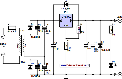
Here's what I've been using with great success. Got it from extremecircuits.net
http://www.extremecircuits.net/2010/05/48v-phantom-microphone-power-supply.html

48-v-microphone-supply-circuit-diagram.png
 
thank you guys, that was exactly what I needed. I will go for the extra transformer.

best regards
Rafael
 
Well, if you gotta have a separate transformer, why not pick the right one and loose the voltage-doubler?
A 48V secondary going directly to a 4-diode bridge has much less ripple than a doubler to start with.
 
ruffrecords said:
You need to remember that phantom power is not just another voltage rail - it is part of the mic preamp input circuit. In order to minimise noise/hum pick up at the mic pre input you really need a completely separate winding or transformer for the phantom power so it is completely isolated from the other power supplies so I would not recommend deriving it from an existing rail.

Cheers

Ian
I don't really agree with that. The only important thing is that the phantom rail reference (whether it is the negative of the last filter cap or the ground return of the regulator) must be solidly tied to the Pin 1 of the XLR. A separate winding makes it just a tad easier, that's all.
 
abbey road d enfer said:
why not pick the right one and loose the voltage-doubler?

If parts are available and affordable... sure.  The solution I posted above is only approximately $15.
I cant find a 48V transformer close to that.
 
abbey road d enfer said:
ruffrecords said:
You need to remember that phantom power is not just another voltage rail - it is part of the mic preamp input circuit. In order to minimise noise/hum pick up at the mic pre input you really need a completely separate winding or transformer for the phantom power so it is completely isolated from the other power supplies so I would not recommend deriving it from an existing rail.

Cheers

Ian
I don't really agree with that. The only important thing is that the phantom rail reference (whether it is the negative of the last filter cap or the ground return of the regulator) must be solidly tied to the Pin 1 of the XLR. A separate winding makes it just a tad easier, that's all.

Which is exactly the problem.  The 0V of the power supply needs to be connected to the chassis at exactly one point  which is the point where the safety earth from the mains input socket connects to the chassis which is as close to the mains input connector as possible. In even the simplest design, the mains socket is unlikely to be close to mic XLR. So, if instead you connect the phantom rail reference to pin 1 of the mic  XLR and this Is electrically the same as the main signal 0V which is connected to the chassis at the mains. Input connector then you have created a ground loop.

Cheers

Ian
 
ruffrecords said:
abbey road d enfer said:
ruffrecords said:
You need to remember that phantom power is not just another voltage rail - it is part of the mic preamp input circuit. In order to minimise noise/hum pick up at the mic pre input you really need a completely separate winding or transformer for the phantom power so it is completely isolated from the other power supplies so I would not recommend deriving it from an existing rail.

Cheers

Ian
I don't really agree with that. The only important thing is that the phantom rail reference (whether it is the negative of the last filter cap or the ground return of the regulator) must be solidly tied to the Pin 1 of the XLR. A separate winding makes it just a tad easier, that's all.

Which is exactly the problem.  The 0V of the power supply needs to be connected to the chassis at exactly one point  which is the point where the safety earth from the mains input socket connects to the chassis which is as close to the mains input connector as possible. In even the simplest design, the mains socket is unlikely to be close to mic XLR. So, if instead you connect the phantom rail reference to pin 1 of the mic  XLR and this Is electrically the same as the main signal 0V which is connected to the chassis at the mains. Input connector then you have created a ground loop.

Cheers

Ian
No, look at the attached schemo. The final cap (or the regulator's reference) must be connected to Pin 1, but pin 1 does not need to be connected solid to IEC ground. One must make sure that the filter arrangement does not create current spikes; using series resistors, chokes and regulators is ok, using shunt regulators is not.
 

Attachments

  • phantom ground.jpg
    phantom ground.jpg
    59.9 KB
I agree the final cap of the decoupling at the mic pre itself must be connected to Pin 1 on the XLR and the XLR pin 1 must also be connected to chassis at the connector. That is not the problem. The problem is that the 0V reference at the power supply end ( downward arrow on the right hand side of your diagram) is also connected to the chassis at the IEC inlet. That is what causes the ground loop.

Cheers

Ian
 
alexc said:
I think multiplying the heater will call for a lot of multiplier stages - i've not used more than 3 or so.
Could be an issue.

Deriving phantom from B+ could be a little hazaardous in the case of component failures.
B+ and performer body parts don't mix well  :)

I would accept that phantom is not really feasible or a different traffo is called for.
An additional investment in a more suitable psu traffo is worth it imho.

Cheers
Better off with the new xfmr or adding an additional one for the job. The isolation of managing the P48 from it's own winding is worth the effort. In all cases I've seen P48 derived from B+ it has not gone well.
FWIW I have seen low power (3mA) B+ (140v) successfully generated with a multiplier off a second heater (12v) winding of the power xfmr.
 
abbey road d enfer said:
ruffrecords said:
That is what causes the ground loop.
There is no ground loop. The two ground symbols are not connected by anything other than the chassis. That's why I've drawn these two grounds with different symbols.

You are absolutely right, there is no ground loop. I just looked up my notes on phantom wiring in mixers. The problem is that screens and chassis should never carry signal current. They carry interference currents and so should take the shortest independent path to safety earth and the signal 0V should be connected to the safety earth at one point only close to the mains input connector. The trouble with phantom power is that the signal 0V is the mic cable screen. If the phantom supply 0V is connected to the chassis at the power supply end then all the noise currents flowing in the chassis between the mic XLR pin 1 and the the safety earth point appear in series with the mic 0V. OK, this is common mode noise but we are injecting it into the most sensitive part of the circuit. The better solution is to have the phantom power 0V separate from the other supplies and connect it directly to pin 1 at the mic XLR.

Cheers

Ian
 
ruffrecords said:
If the phantom supply 0V is connected to the chassis at the power supply end then all the noise currents flowing in the chassis between the mic XLR pin 1 and the the safety earth point appear in series with the mic 0V.
The idea of using pin 1 as the reference for phantom is that it allows "remote-ing" this reference. The Ov of the first reservoir caps is then allowed to float as much as chassis layout and construction allow.
OK, this is common mode noise but we are injecting it into the most sensitive part of the circuit.
This would be the case whatever the arrangement; as long as the mic cable screen is referenced to Pin 1 there is common mode noise. The only way to eliminate CM noise would be to tie the preamp's audio ground to Pin 1. This may be discussed...
The better solution is to have the phantom power 0V separate from the other supplies and connect it directly to pin 1 at the mic XLR.
It's a simpler solution, but I don't think it has a definite advantage. The only problem with my proposed scheme is that the current from the regulator/last cap may introduce spikes in the return path, which would be a problem if the filtering and grounding arrangement were incredibly poor.
The "problem" would be the same when using a voltage-doubler from a 2x18V transformer, a very common practice in SS mixers. having used this a number of times, I know for certain that "remote-ing" the reference cleans up any phantom related noise. 
 
abbey road d enfer said:
ruffrecords said:
If the phantom supply 0V is connected to the chassis at the power supply end then all the noise currents flowing in the chassis between the mic XLR pin 1 and the the safety earth point appear in series with the mic 0V.
The idea of using pin 1 as the reference for phantom is that it allows "remote-ing" this reference. The Ov of the first reservoir caps is then allowed to float as much as chassis layout and construction allow.

I am not at all clear about that. I think the problem is illustrated by the attached sketch:

The question is where to connect the phantom power supply 0V as referenced by the ?? in the sketch. If it is connected to chassis at some point remote from the XLR pin 1 then all the noise in the chassis between those two points is injected in series with the phantom supply. The problem is not whether the balanced connection can reject this CM noise in the screen but whether the electronics in the microphone can reject it. One thing is clear though, the amount of such noise is minimised if the 0V from the phantom supply is connected only at the mic XLR pin 1. This is not a simpler solution because it requires a separate winding for the phantom power supply so its 0V can be isolated. In my view it is the one supply that should NOT be connected to chassis at the safety earth point.

Cheers

Ian
 

Attachments

  • phantomnoisecct.jpg
    phantomnoisecct.jpg
    85.4 KB

Latest posts

Back
Top