Scodiddly
Well-known member
Just thought I'd stick this here for reference - I originally wrote it up to answer somebody's email request.
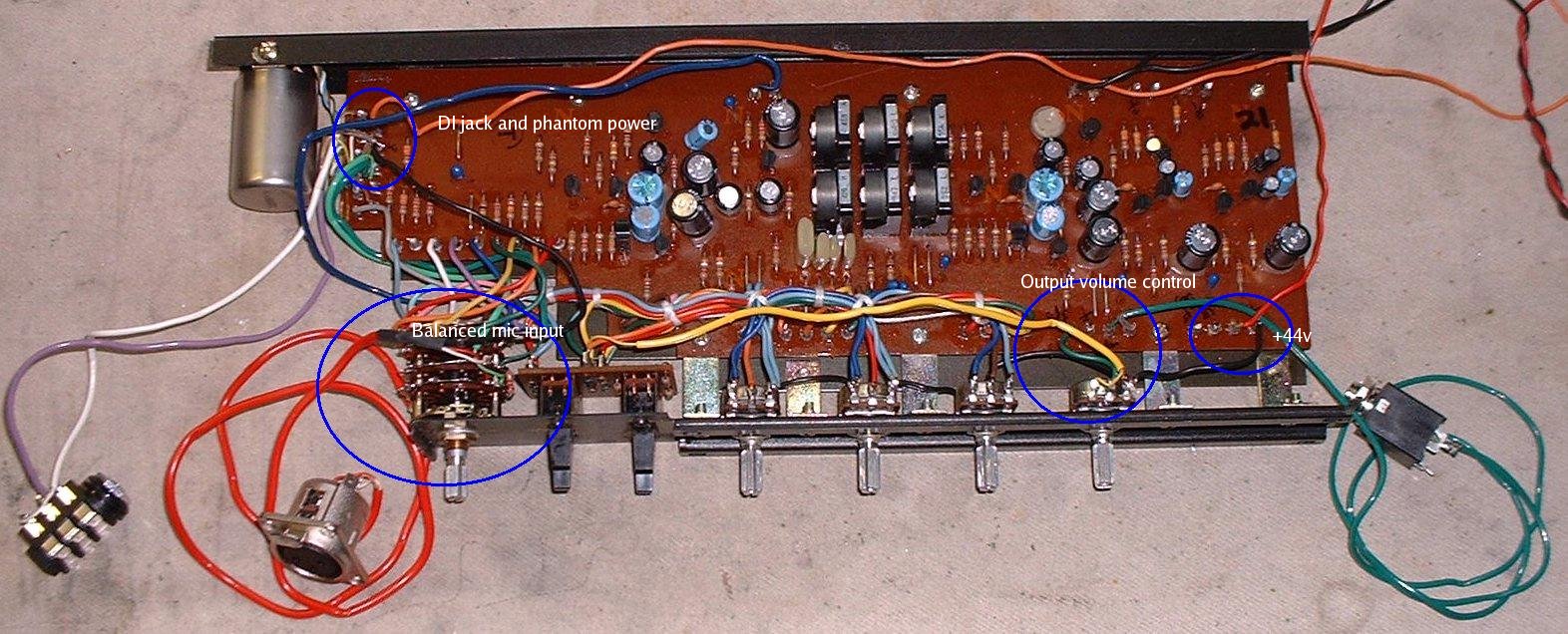
(click for full-sized image)
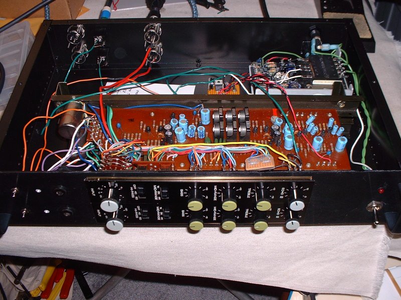
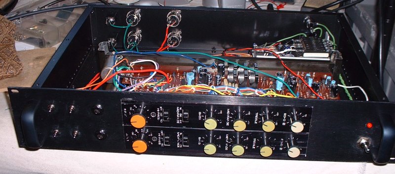
Attached is a picture of a cut-down PM-1000 module for rack mounting. You
can really figure it out by just cutting off all the wire ties and
tracing the wires, since things are wired up in a fairly obvious way.
What I did was to remove all the panpot and buss assign stuff, the fader,
etc, and then rewire the Echo 2 pot as main fader. The final output
(before any output transformer) is just taken from where the
panpot/assign stuff was connected.
1. Mic input is the red cable attached directly to the stepped input gain
switch. In the stock module the red cable just runs up to the big
connector, but you can just solder an XLR onto it instead.
2. DI input and phantom power are down by the input transformer (silver
can on upper left of picture). The DI is just a normalling jack between
the transformer output wire and the last circuit board connection. The
phantom power comes in via the orange wire connected right next to that.
3. The Echo 2 knob is now the main fader - there's a yellow cable coming
from the little circuit board behind the low-cut and mid-frequency
switches which originally connected to the fader pot, but which is now
connected to the echo 2 pot instead. The cable that came from the output
of the main fader was removed and a short piece of wire used to connect
to the output of the Echo 2 pot. Finally, the green cable to the output
is connected where the panpot used to be connected (brown cable in the
original). The output can go to a transformer or just be an unbalanced
ouput as shown.
4. The +44vdc main B+ power connects here via the red wire.
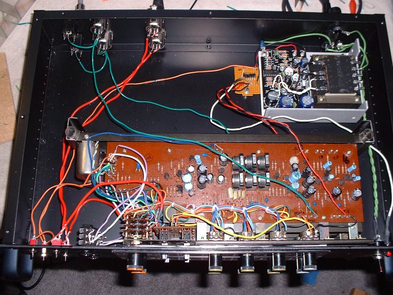
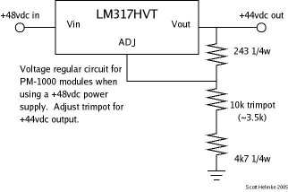
Power supply I've used is a 48vdc power supply from Digi-Key, part #
179-2034-ND. Supposedly you can tweak it to run at 44vdc, but I just put
a few (6 or 7?) 1N4003 diodes in series to drop the voltage to ~44 (each
diode drops the voltage a little). Next time I'm going to use the same
power supply but with a more conventional LM317HV regulator circuit.
(click for full-sized images)



![Electronics Soldering Iron Kit, [Upgraded] Soldering Iron 110V 90W LCD Digital Portable Soldering Kit 180-480℃(356-896℉), Welding Tool with ON/OFF Switch, Auto-sleep, Thermostatic Design](https://m.media-amazon.com/images/I/41gRDnlyfJS._SL500_.jpg)


