Polarization Scheme for m221b

GroupDIY Audio Forum

Help Support GroupDIY Audio Forum:

This site may earn a commission from merchant affiliate links, including eBay, Amazon, and others.

SparkleBear

Well-known member
GDIY Supporter
Joined
Jun 21, 2016
Messages
311
Location
Santa Cruz, CA
Hey all,

Im working on a mxl to m221b mod right now. I will be using the 3u capsule and I don't think they can handle the 120v polarization that the original circuit calls for...

Stock schematic (with 10uf filter cap added):
1671997553001.png

I had a few questions about how to implement a divider circuit and also a few questions about component functions.

First, in the stock circuit, what is the purpose of the R6-500k resistor that connects anode to to ground?

Next, I was thinking of adding one resistor pre R4 to create a voltage divider with the 100k+500k resistors as the shunt leg of the divider. So to give 60v at capsule, i would add a 600k resistor on the b+ input line... but that would mess up the plate resistor value (seeing 600k before b+) and the plate would see a lot less voltage than it needs so thats probably wrong...

So, what about a 50k/50k divider like this so the plate still sees 100k between itself and b+ but the capsule will get a B+/2 voltage level...

1671997928506.png

Would that work or would I also want to drop the 500k to a 450k to retain some sort of balance?

Any reflections would be helpful for my process here. Thanks so much! :)
 
You might be slightly overthinking(?) things.

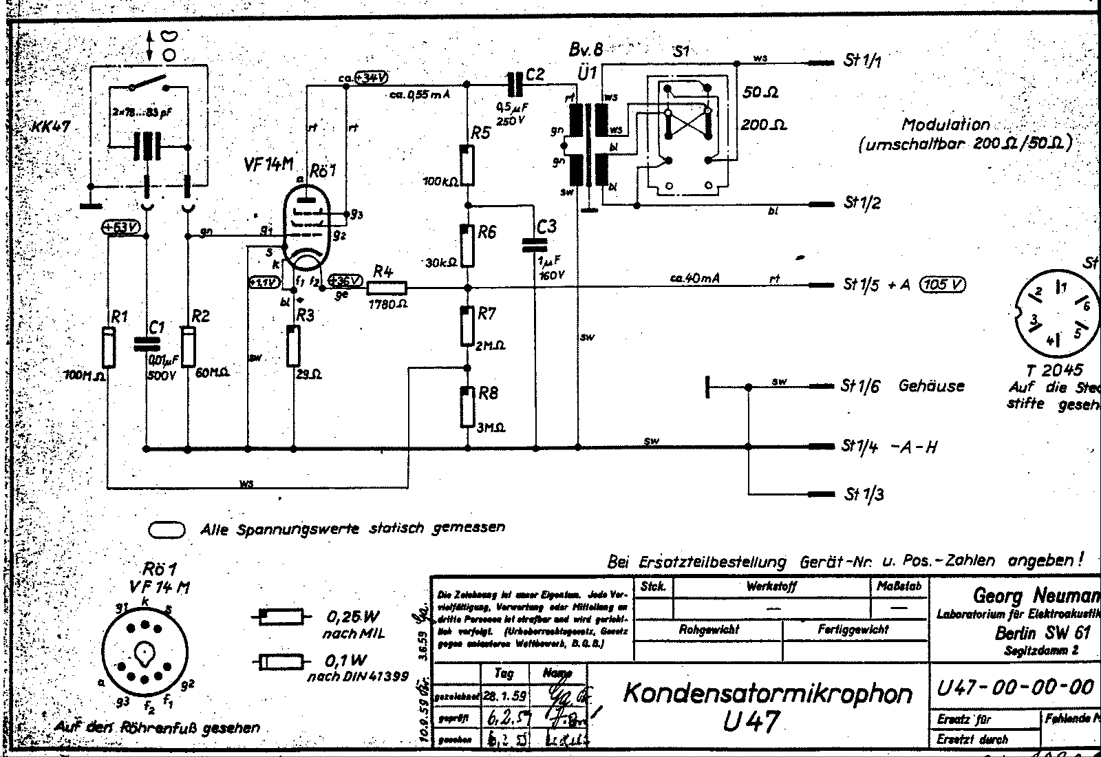
Leave all the components as they are, just disconnect the B+ end of R1, and connect it to the middle of a, say, 1M + 1M divider, between B+ and ground.

ExHphiQ.gif


In the case of the above-pictured U47, that would be the R7/R8 divider. You might also want to include a ~100nF cap or so, in parallel with the bottom resistor of the divider, for some extra filtering.
Ahh, thanks for always helping me sus things out Khron...

So this:
1672000090435.png

Whats the benefit of using a 1M/1M divider VS a 200k/200k for example?
 
Ahh, thanks for always helping me sus things out Khron...

So this:
View attachment 102037

Whats the benefit of using a 1M/1M divider VS a 200k/200k for example?

Given a certain capacitor value, the cut-off frequency of the low-pass filter is lower with 1M than 200k. And you load down the B+ rail less, but that's virtually a non-issue in the real world.
 
You might also want to include a ~100nF cap or so, in parallel with the bottom resistor of the divider, for some extra filtering.
I am very tight on space... what kind of composition capacitor would you recommend on this position for filtering the shunt leg of the divider? Film might be too big... lytic?? what do you think? This is likely going to have to fit on the back of the circuit board which has a lot less clearance than he top...
1672001543255.png

Yours looks like a modification, not sure if that one is original. Where is the schematic from? (@rock soderstrom )

I got it from Robert at RMS audio...
 
I am very tight on space... what kind of composition capacitor would you recommend on this position for filtering the shunt leg of the divider? Film might be too big... lytic?? what do you think? This is likely going to have to fit on the back of the circuit board which has a lot less clearance than he top...
View attachment 102041

What microphone is that? Cause i don't see any tubes there... Or will that be the donor body for the circuit you're asking about?

Film caps should be fine; i know for a fact that 10nF / 250v can be found in 2.5x7.5mm through-hole packages. The 100nF i suggested was just a ballpark "standard" value; 10 to 47nF should work just as well. You see there's no extra filtering in the U47 anyway.
 
Be careful this schematics will add 120v to the capsule, there were multiple mic versions for schoeps 120v and 60v capsules(I dont remeber the codes sorry).the 120v will destroy the current remake capsules.
Im working on a mxl to m221b mod right now. I will be using the 3u capsule and I don't think they can handle the 120v polarization that the original circuit calls for...

It sounds to me like that was already accounted for... Which is the whole point of this thread, as i see it.
 
What microphone is that? Cause i don't see any tubes there... Or will that be the donor body for the circuit you're asking about?

Film caps should be fine; i know for a fact that 10nF / 250v can be found in 2.5x7.5mm through-hole packages. The 100nF i suggested was just a ballpark "standard" value; 10 to 47nF should work just as well. You see there's no extra filtering in the U47 anyway.

That was just the donor body, i put the photo there just to show the clearance underneath the pcb. This is the custom PCB that is the same size as the original board... just a swap... and 3u capsule upgrade from the crap mxl capsule.
1672005395858.png 1672005476862.png


This is the board as it is after the polarization voltage divider.. I found a tantalum capacitor that is small enough and put it behind the output cap... but I will look for other film caps that will clear the underneath.

Im not sure if i need that extra 10nf electrolytic filter on the heater line... its getting pretty stuffy on the board ;P
 

Latest posts

Back
Top