Power supplies and smaller p2p boards for 2ch tube preamp

GroupDIY Audio Forum

Help Support GroupDIY Audio Forum:

This site may earn a commission from merchant affiliate links, including eBay, Amazon, and others.
My3gger said:
After checking Ian's phantom supply with TL783 it looks like 2W 4k7 resistor would act as fast ramp down of output voltage. My thinking is 4k7 takes minimum current required by TL783 and output cap isn't so big it would take longer time to empty it.
So this should be ok in cases someone turns off phantom and right away connects something phantom could damage. I had situations myself when a few seconds more of phantom could damage something.
The speed and time of ramp depends on how much charge is in the main smoothing capacitor. My design is intended for a mixer and can supply up to 100mA of phantom power. That is why the reservoir capacitor is so large (4700uF) For a single channel you can safely reduce this the 470uF and it will ramp down 10 times faster.
What about slow ramp up as needed for V72 trafos and similar, can't find another reason for it, maybe they are? There is some delay before cap is full, maybe not enough for very tiny windings? Does regulator takes care of this, can't find it in datasheets, i know it is short circuit proof.
I have not heard of a need for slow ramp up for V72 input transformers. There is no dc across the winding if you use a pair of 6k8 resistors  - or are you feeding phantom to a centre tap?

Cheers

Ian
 
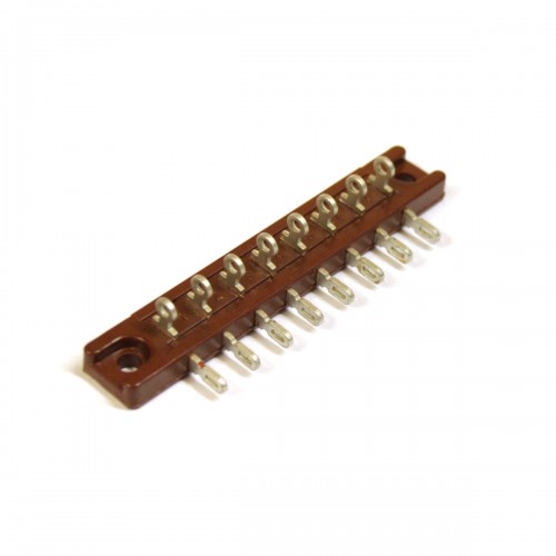
Sorry for ad, for p2p soldering old russian tagboards are good choice imo.
Tag-Board-RUS-L8-0-500x500.jpg

Various types and sizes available. No need to mount turrets, pay for board material etc. and they are really good quality and reliable military stuff.
 
ruffrecords said:
The speed and time of ramp depends on how much charge is in the main smoothing capacitor. My design is intended for a mixer and can supply up to 100mA of phantom power. That is why the reservoir capacitor is so large (4700uF) For a single channel you can safely reduce this the 470uF and it will ramp down 10 times faster.I have not heard of a need for slow ramp up for V72 input transformers. There is no dc across the winding if you use a pair of 6k8 resistors  - or are you feeding phantom to a centre tap?

Cheers

Ian

Most test i do on audio gear like preamps is from DC player through line-mic pad and into mic input. Often unbalanced and sometimes switching fast.
Here is thread about V series high ratio trafos (1:30 like in V76 and lower too) possibly being damaged by phantom if it doesn't have slow ramp up. Oliver Archut mentioned ~5 seconds which seems a lot to me and a lot of people never had problems with such trafos. Maybe it wasn't about phantom  but detoriation of wire...
https://groupdiy.com/index.php?topic=280.0
Reply #14 mentioned RC filter on phantom switch as Jensen's i use. This values give 85ms of delay, Hansen's filter 387ms. His rampdown seems a little slower at about 1sec, can't remeber if i used 1k with 100 or 220uF, later has a bit under 1 sec ramp down delay. Thinking a bit more i don't see real reason for not using TL783 and maybe add Hansen's output RC instead of Jensen's. I didn't have thumps or any other problem with either.


ungifted said:
Sorry for ad, for p2p soldering old russian tagboards are good choice imo.
Tag-Board-RUS-L8-0-500x500.jpg

Various types and sizes available. No need to mount turrents, pay for board material etc. and they are really good quality and reliable military stuff.

I like suggestions like this and was searching for your shop too, so thanks. The thing with those tagboards is lack of insulation when fixed on the bottom of chasis. Good for home, not so much if gear is moving around and used a lot. I will see how this smaller turret layout goes, if i find i was too woried tagboards could be mounted on board without predrilled holes. It is not the last piece of gear i'm making :) Quality of this stuff is very nice, i used it before.
 

Attachments

  • Jensen mic input circuit.pdf
    11.6 KB · Views: 11
My3gger said:
Thinking a bit more i don't see real reason for not using TL783 and maybe add Hansen's output RC instead of Jensen's. I didn't have thumps or any other problem with either.

My phantom power supply is just a power supply. I also use an RC on the mic pre board it supplies.

Cheers

Ian
 
ruffrecords said:
My phantom power supply is just a power supply. I also use an RC on the mic pre board it supplies.

Cheers

Ian

Hi,

found your phantom filter with iirc 47u and 100r, not far from Jensen.
I never seen RC filter like on Bo's schematic where only C and 6k8 resistors are after switch. Don't know why did he draw it this way, i put 1k resistor after switch so capacitor can bleed. In one pm he mentioned each channel needs separate RC, maybe it was only schematic error:
http://www.hansenaudio.se/API%20psu.jpg

Do you find 47u caps into ADJ pin of regulators necessary even for 1-2ch? My previous regulators didn't have them and were quiet, although better ripple rejection is not a bad thing. Adding it veroboard isn't hard at all either. Even 1 or 2 snap-in caps hold well without glue, that is years of studio use, rarely live.

Farnell now only sells quite wide horizontal heatsinks for 2 TO220 at ~ 7C/W, they used to be a little longer but not so wide before. This might force me to mount them on side panel which gives better heat dissipation. That most likely means use of 3H chasis only because of that counting height of capacitors that might get in the way if it is lower. At first i wanted 2H version and a little more sturdy chasis like old LA-2A and similar.
Gyraf shows simple Al L profile of about 2mm/50mm long that wasn't meant as a heatsink, part of it is beneath the board. LM317 there dissipates more than LT108x, so it should work if insulated.
 
Hi,

i just want to update this a little, others might benefit from my experiences and Ian might be curious how it is going.
Because it is 2ch for live and studio use, modifications might be made and output transformer on one channel closest to psu replaced, i had to order from several shops. It took me about one month getting correct board with turrets, the rest wasn't fast either (always the same here), fortunately i bought transformers before starting.
It took me many drawn revisions with all this material and p2p construction. Mostly for psu because each channel has one for ease of heat managing, groundings, no interaction, possible voltage changes, etc. Getting it on 100x100mm board which allows turning transformers, adding tube covers and similar wasn't easy at all. I made one partial prototype with old material to see how much space it will take while remaining cool, i changed HT from Ian's RC filters to similar but added zeners. The rest is similar as on his website, of course with some modifications. Getting right components also took more time than typical for such psu because smaller were needed, i had to turn it around every possible way to mount regulators on heatsink mounted to side panel. Avoiding long runs and much crossing of AC was probably biggest challenge. So it took a lot of thought and also some help, thanks Ian.
I could get amp on ~19cm long board, layout is very effective, of course by drawing like 7 revisions and checking many datasheets. So now that i got all of important material i'm finally soldering without second thoughts, knowing there will be enough space and good mechanical design. What is left are decision of 2 or 3H rack, front layout is mostly done, so i have to mount inside rack, make controls, get another order and that's it.

One thing i'm wondering about; it would probably be good having tube covers even when sockets are Belton, i have to make sure tube stays inside without checking this too often. One smaller problem with it is XLRs on the back and front controls come on the way when taking covers away, this can be solved with deeper and reinforced chasis. Tubes are mounted horizontaly, did anyone had problems with heat when this was done inside closed rack? I see many don't use covers, like Tab-Funkenwerk.
 
My3gger said:
. Tubes are mounted horizontaly, did anyone had problems with heat when this was done inside closed rack? I see many don't use covers, like Tab-Funkenwerk.

No problems at all. Tubes get a bad press for being huge heat generators but it is really only power tubes that do this. Preamp tubes, whilst hot, do not generate nearly as much heat. I run a pair of 6922 tubes and a 12AX7 in a 3U high 2.8inch wide  160mm deep fully enclosed module. Heaters dissipate 6W and HT about 4.5W - just over 10W total. Front panel gets slightly warm is all. You can mount 6 of these in a 19 inch rack. Imagine a 60W incandescent light bulb inside a 19 inch rack case.

Cheers

ian
 
Thanks. When mounting output driver tubes (like ECC88, 6CG7, 6N6P) near transformers i only noticed bulb temperature high to touch, while transformers don't get almost no heat from them.
My question is about tube covers/shields, could they cause problems to tube? Using them will complicate things just a bit, much better than repairing problems if only part of tube is in socket.
Recording the Beatles mentions E88CC was replaced very often because of cooling problems. Hope this information is correct, for sure it is there. Tubes there are mounted verticaly like in V72. Metal under E88CC socket looks burned to me more than many American designs with similar tube heat, metal under EF86 socket is clean because of so little power. I added this picture, upper part is not higher than tube with socket and shield. There is black shield on this picture for both tubes, good E88CCs also had black internal shield to help dissipation, might be military thing because i mostly see silver shields.
 

Attachments

  • RED47-12.jpg
    RED47-12.jpg
    206.3 KB · Views: 50
> Metal under E88CC socket looks burned to me

To my eye, there's dirt rising up from the big green power resistor.
 
They do run the E88CC at a quite high current in the REDD47 (just over 9mA) with over 140V on the anode which is a total anode dissipation of 2.5W and the data sheet says the total should not exceed 2W so they are pushing it a bit.

The 8K2 anode resistor also dissipated 2,5W so this needs to be really chunky - I would recommend a 10W type.

Cheers

Ian
 
Green resistor should be 8k2 for anode. And yes, burned metal is closest to it, so heat didn't came from E88CC.

If leads are long enough and has some space between it and  bottom of the board, 8k2/5W cement wirewound resistors and their surroundings are ok after years. Even better are two parallell 3W metal films of similar value that make 8k2 or a little more. With same mounting as single resistor they have more area for dissipation and get less warm. Haven't noticed value drift with any option, or signs of burning.

Jonte Knif uses orange tube shields over horizontaly mounted ECC88 input tubes in his Therapy Pre, values show they are well under max dissipation. Output E81L is longer with retainers as on EL84 and similar. Fearn also uses tube shields inside rack mounted verticaly, Tube Tech products i see used live most often don't with the same mounting as Fearn.
I don't see much use of shields on horizontaly mounted small signal tubes, not sure why. Got enough space to put them on anyway because it will be moving around a lot. It is interesting to notice EH E88CC has thicker glass than others i've seen, they run 10+ degrees warmer at 2,5W.
Local guitar amp tech and i compared EH to JJ, those look chemicaly and mechanicaly inferior. He discards and replaces a lot more small signal tubes from them, compared to EH. JJ cost about half price and many people want them...


My3gger said:
Local guitar amp tech and i compared EH to JJ, those look chemicaly and mechanicaly inferior. He discards and replaces a lot more small signal tubes from them, compared to EH. JJ cost about half price and many people want them...

That mirrors my experience. JJ are very variable. EH are consistently good.

Cheers

Ian
 
> more area for dissipation and get less warm.

Mounted in the same area, it will be the same amount of heat, and about the same hot-spot hot-air convention putting air-dirt on the surface above it.

That's not a lot of dirt if this amp has been run thousands of hours over the decades.

The metal is not burned. Just dirty.
 
Back
Top