Preferred way of attentuating an input signal?

GroupDIY Audio Forum

Help Support GroupDIY Audio Forum:

This site may earn a commission from merchant affiliate links, including eBay, Amazon, and others.

Svart

Well-known member
Joined
Jun 4, 2004
Messages
5,134
Location
Atlanta GA USA
Need to stick an adjustable attentuator on the input of my DI. I know there are many ways to do this but wish to critique different ways and determine the best to use.

these are my ideas so far:

1. jack-cap-rheostat to ground?
2. jack-cap-rheostat in line?
3. no cap in either?
4. another way to do this?
5. drink heavily until i don't care?


:green:
 
Use a pot. Signal to high side of pot, output from wiper, low side of pot to ground.

Since this is for a DI, the value of the pot will need to be pretty high to avoid loading down your guitar/bass pickup. What's the input impedance of your DI?
 
it's gonna load exactly the same way the volume knob on your guitar/bass will... if you want to avoid the loading, you could go with an input buffer in front of it, but it becomes a bit more complex at that point :)
 
Not exactly, since a pot directly at the DI input is only working into the input capacitance of the DI, as opposed to the input capacitance of the DI plus that of several feet of shielded cable.
 
right now it's based on the simple dual JFET di that was in a posting on here a while ago. the signal to ground resistor was originally set at 20meg. using this as is allows the guitar bass to run directly into the DI, but it clips fairly badly on loud strikes or hot pickups straight from the instrument. you can forget about DI from pedals without seriously turning the outputs ALL the way down.

experimenting with the pot idea that NYD just mentioned showed me that not until i get down to 8 ohms does the signal from the effects pedals become usable. this will be the main use for these DIs. I used the cap-resistor to ground around 8 ohms and it has been working for a week just fine but something just keeps telling me that this is not right. should i place the 20meg load back in BEFORE the cap? as in an earlier topic, i don't know much about input impedence and there hasn't been much explaination beyond " XXXX is the RIGHT impedence" but everyone has their own idea of the RIGHT impedence and each mic and instrument seems to like something different. :sad:

so i guess i must ask, how do you FIND the optimum impedence without just knowing it?
 
For a DI the ideal impedance is going to depend on the instrument, so you're going to have to experiment.

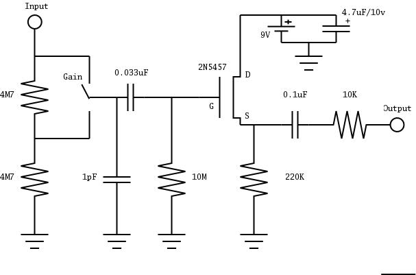
I did a little FET buffer box for piezo pickups recently, and on bass it overloaded a bit. So what I did was put a couple 4.7M resistors in series in place of the original 10M input resistor, and added a little jumper so you could "pad" the input. It's really the same thing as that potentiometer circuit mentioned above, usually called a "voltage divider" circuit.

Mint-box-buffer-schematic.jpg
 
What Sco just posted works great for an -8dB level drop... IF you eliminate that 20pF cap, which is giving you a huge high-frequency rolloff when the attenuator is switched in (-16dB at 10kHz, or -8dB relative to the overall insertion loss). If you need more attenuation, or you want it to be continuously variable, replace those two 4.7M resistors with a 1Meg audio-taper pot. Connect your input signal to the high side of the pot, ground the low side of the pot, and connect the wiper to the input coupling cap.

1Meg in parallel with 10Meg is 900K, which is plenty high for most coil-type guitar and bass pickups (but may not be high enough for passive piezo arrangements).
 
Svart: quick impedance lecture as I learned it:

the relationship between output impedance and input impedance is the same as the way a voltage divider works. If the impedances are purely resistive, you can look at it like this:

if you have a stage that puts out 10V unloaded, with an output impedance of 1k, and you feed that to a stage that has an input impedance of 1k, then the loading that happens is that you have:
(ideal voltage source, 10v) -\/\(1k)/\/\- (A) - \/\/\(1k)/\/\-- ground

The point (A) is the actual input of the second stage. The Zout and Zin form a resistive voltage divider, which causes the voltage at point A to be exactly half of the ideal (unloaded) output voltage of the first stage.

If the impedances have a reactive component, then the voltage drop is frequency dependent.[/u]
 
hmm.. I guess i've worked with video circuits too long because i am used to a standard 75R USA or 50R EURO load on either end of the cable regardless of voltage.

i'm going to open pandora's box here and act completely ignorant of this and ask a few questions.. maybe we can put the answers in the noob thread.

what is output impedence and how do you measure it?
how can an output have impedence since outputs are generally defined as DRIVING an impedence?


how can a transistor have output impedence and/or what if the output of a device is solid state and the input of the following device is also solid state?

also:

I use opamps and FETs for inputs/outputs, how can a switch like this have impedence other than infinity or 0 ohms?

why does input impedence matter if the output of a device can drive it ok?

also:

if the output of a device can drive XXX impedence are the only constraints the ability of the input of the driven device to handle the current flow induced?

I can think of many more questions that might be asked but lets start with those.

:guinness:
 
[quote author="NewYorkDave"]What Sco just posted works great for an -8dB level drop... IF you eliminate that 20pF cap, which is giving you a huge high-frequency rolloff when the attenuator is switched in (-16dB at 10kHz, or -8dB relative to the overall insertion loss). [/quote]


Oops. I'll have to look into that. I hadn't noticed any issues, but then that's the "bass pickup" setting anyway. You'd be amazed at how much voltage you get from a piezo pickup on a bowed upright bass!
 
> pedant!

Not at all. Capacitance always bites the highs.

I once rebuilt an oscilloscope, pots in front, amp in the rear. That minimized deflection-plate capacitance. BUT the cable from front pots to rear amp rolled-off 20KHz pretty bad at medium gains.

This may be less of an issue with guitar-range signals, and piezos. But still has to be considered.

> i've worked with video circuits too long because i am used to a standard 75R USA or 50R EURO load

Right. You think 20KHz is tough, try pushing 20MHz down a few feet of wire. In that situation, even 100 ohms of resistance is "high" compared to the pFd and MHz.

BTW: US practice includes both 50/52Ω and 75Ω systems. Short or high-power runs are often 50Ω. Cable-TV systems are universally 75Ω because it uses less copper (less cost per mile) and absolute gain flatness isn't needed (you are only looking at one 5MHz band out of the total 300MHz signal).

------------------

> how can an output have impedence since outputs are generally defined as DRIVING an impedence?

EVERYTHING has an output impedance. Look at Hoover Dam's gigantic generators: Put one light-bulb on them, and you can hardly measure the voltage drop, but hang all of Las Vegas and half of Los Angeles on them, the 10,000 volts no-load sags to 9,000 volts at (say) 9,000 Amps. Hoover Dam has an (uncompensated) output impedance of 1Ω.

Small vacuum triodes have about 10KΩ output Z. Pentodes and BJTs about 1MegΩ.

Cathode followers around 1,000Ω, emitter followers around 10Ω, BUT these things are "feedback". They self correct their output voltage. Same over at Hoover Dam: they don't let the output sag 10%, some guy (or box) turns-up the field to keep a pretty constant voltage. If done perfectly, we have 10,000V at 0A or at 10,000A, and the output impedance seems to be "zero". However this does NOT mean we can put a 100,000A or 1,000,000A load on Hoover Dam and still get 10,000V or even 9,000V: at some point you can't turn-up the field enough to hold voltage, and/or smoke starts pouring out of a million dollars worth of copper windings. (Actually, Hoover's hydro-turbines will probably slow and stop under heavy loads; not too unlike how a soft triode goes rounded.)
 
the only thing with a zero output impedance is an ideal voltage source, which as far as I know doesn't exist :D A Voltage source with a 0ohm Zout wouldn't drop AT ALL if you short circuited it - get the picture?

output impedance is generally defined something like 'resistance to the ability to source current', or something along those lines. It can be measured by placing some known resistance across it, and measuring the drop. If you have a circuit providing 10V at no-load, and load it with 10k, and it drops to 9v, you draw yourself a voltage divider with 10k on the bottom, your mystery Zout on top, 10V in, and 9V out, and solve for X :)
 
thanks!

Oh yes I know much about pushing video to it's limits! we frequently send video down 1kft of coax with about 20 ohms resistance.. those driver ICs and transistors get fairly warm. some outright fail if a connector gets corroded and a high-z situation forms. we also get a lot of burned up 75R resistors because of shorted wiring and/or water damage which usually kills everything else in one great smoke show.

well I do understand what everyone is saying, but when we say impedence of a device, that assumes some kind of perfect coil because we never really talk about the current handling ability of the coil or device. 100 ohms may not be a lot of impedence, 10k ohms is more for sure, but if the 100 ohm wire is 30 ga and the 10k is 10ga wire, then given a couple of amps at any voltage the 30ga will likely burn up, the 10 ga will get hot but probably not burn up.

so my thinking is this.. impedence is surely nothing without knowing the current capability of the output device and that of the input device.

so i look at this impedence matching more like that of current capability(because that is what I've learned to worry about more i suppose)

so this would be my view of the Hoover dam generators (or are they alternators?). they are equiped to push a maximum current which is in direct relationship to the impedence of the powerlines and end devices at a certain voltage level. i see the voltage level as the constant here, the impedence and the current levels are the variables.

audio is slightly different though since the impedence is usually considered the constant and the voltage and current are variables. yes it's all ohm's law but the thought in the design is different.

so why aren't we making all the microphones have the same current drive ability so that we can standardize input current handling (impedence goes hand in hand here, but the current pulled from improper matching is what really kills parts...) so we don't burn up stuff?
 
What made the lightbulb come on for me was trying to understand how an R2R ladder works, which I was mucking about with in order to get multi-bit VGA from an FPGA.

The FPGA puts out 3.3V on its IO pins.

VGA specs say that it wants a color signal on the RGB pins between 0 and 0.7V, with 0 being black and 0.7V being full scale of whatever color that pin drives.

VGA also has a 75 ohm terminating impedance on the other end.

The manual for my FPGA devboard said that it had a 270ohm series resistance between the IO pin and the RGB pins on the VGA connector.

So here I am, trying to figure out wtf this all means, and scribbling on a piece of paper.

Guess what - 270/75 voltage divider: Vin * R2/(R1+R2), 3.3 * 75/345

... 0.717V!

If the 270 ohm series resistance wasn't there, the Zout would have been the (likely much lower) natural Zout of the FPGA IO pin. If the 75 ohm terminating resistance on the other end of that cable inside my monitor wasn't there, the Zin of the monitor's RGB lines would be the (likely much higher) natural Zin of those particular circuits. The result would have been that the voltage likely wouldn't have dropped much, if at all. That would have been very bad in this case!

But in most cases, that's exactly what we want! We dont WANT our signals to be loaded! We want them to be examined, sampled, processed, minced, julienned, whatever we must do to them, all while not affecting them.

Most of the circuits we build are amplifiers of some kind. The theoretical "perfect" amplifier has infinite gain, perfect linearity, infinite input impedance, and zero output impedance.

Svart, come check out my GSSL! I hope to finish it up very very soon, just waiting on the power trafo! I'll show you the magical book which made all this clear to me- "The Art of Electronics", horowitz & hill. It's a pricey beast, like $80, but it is SO worth it. There are a ton of concepts in it that were difficult for me to grasp from other texts, but they made it so clear.
 
Btw, the actual R2R ladder has another 'AHA' story behind it that I love to tell... if anyone cares :shock:
 
well, to clear things up a bit, I'm not asking these questions for myself, I'm trying to make a point here. I can find the answers if i need, I'd jsut rather try to make it a learning experience for all. I guess i'm falling short of making my point it so i'll just say it.

in short, it seems that there is no clear protocol to follow when producing something to market to the masses, that there is no standard. what I'm talking about includes things like impedence, voltage and current. do we set impedence of all devices to some arbitrary number and allow current and voltage to vary? Do we set voltage levels and allow impedence and current to vary? and so on.. I also tried to ask questions that would raise eyebrows to the fact that impedence really means inequality in a driver-driven relationship, that we set ranges of the three parts of ohm's law and hope that whatever we design will work with some percentage of the user's equipement.

we as designers should set a standard to insure proper working order for all devices. just about every other serious electronics sector has such.

I'm sure that someone will voice the opinion that we shouldn't standardize because we run the risk of painting ourselves in the corner by limiting our options. well i say that we will actually open doors because we can design parts to work optimally with ALL equipment. we don't have to change the topology, just make sure that it's input/output conform to a standard that frees us from the guessing game.

wouldn't it be nice to grab an effects processor and not worry about if it's +4 or -10? wouldn't it be nice to plug a mic in and NOT have to jack the gain up to 60 to get a usable signal? wouldn't it be nice if ALL mics were sure to have the same impedence and there would be no problems with frequency spiking because the impedence is too mis-matched?

that's all i was saying... :green:

hey and just set a time/day TMBG and I'll bring my GSSL too!
 
Back
Top