Problem with a Tube guitar preamp project .....

GroupDIY Audio Forum

Help Support GroupDIY Audio Forum:

This site may earn a commission from merchant affiliate links, including eBay, Amazon, and others.
> drop the plate resistor to well below Rp of the tube which is a nono.

No no, not a no-no, not for this case.

Paia did NOT want a "good amplifier". Distortion, overload... everything bad is good.

For Paia's values, Koren 12AX7 model, 70V supply, I get plate sitting near 40V, cathode near 0.3V, one-stage gain gain near 22, 7Hz-70KHz. Gain rises very little at 150V and 300V supply. 1Vpk input gives +15V(squished) -22V output for 70V supply, +23V -24V output for 300v supply.

I won't argue Curtis' 26V 0.15mA values, because real 12AX7 vary a LOT at low current. The idea is the grid is awful close to the cathode; how-close varies a lot between factories and production lots. And then each model is based on different measurements, and most are extrapolating their buts off at very small current.

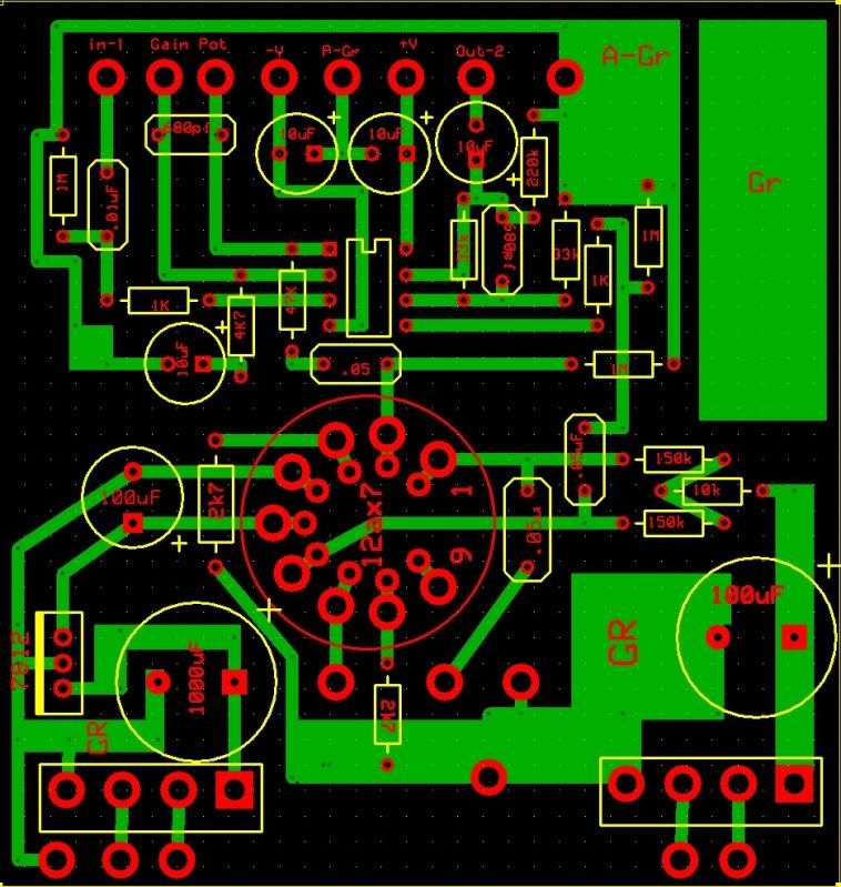
Why is it acting bad? It has WAY too much gain. Is it built on Paia's PCB, or is it home-brew? Do you have experience with HIGH-gain amplifiers?

If you just want a gitar preamp, there are much better paths. Steal the first two stages and layout from any Fender Blackface. The AA-Champ is a fine reference.
 
> drop the plate resistor to well below Rp of the tube which is a nono.

Triode is just a goofy resistor, with a resistor-multiplier factor.

It is hard to get "no" current from a triode. Conventional triodes may pass mighty low current at low voltage; the 12AX7 is gimmicked and will pass quite a lot of current at low voltage.

Leaving specific tubes aside: there are some guides which will usually get you a "working" operating point.

Let:
RP = plate resistor
Rp = tube plate resistance, nominal
Rk = cathode resistor
Mu = tube amplification factor

And for this case:
RP = 270K
Rp = 60K at 1.4mA (maybe more like 180K at low current)
Rk = 2.7K
Mu = 100

The tube will act approximately like a resistor of:
(Rk*Mu)+Rp
(2.7K*100)+60K = 330K
or
(2.7K*100)+180K = 450K

The ratio 270K/330K or 270K/450K will set the plate at 45% or 63% of supply voltage. For 70V supply, 31V or 44V, somewhere in there.

Conversely, you can select RP at whim, within reason, then divide by Mu to get a trial value of RK. 270K/100= 2.7K, just as Paia picked.

A more valid expression could be 0.6*(RP+Rp)/Mu. This accounts for the total tube resistance, plate plus bias. It does require a good guess of Rp at the final operating point. Since the maximum possible current, 70V/270V, is just 0.26mA, the 1.4mA spec value is surely too high. 0.6*(270K+180K)/100= 2.7K trial RK value.

Any of these will probably work. (Especially since it keeps coming back to 2.7K).

If, instead, we select RP at 10K, and guesstimate 60K Rp, then the simple formula RP/Mu suggests RK = 100 ohm, and the long formula 0.6*(RP+Rp)/Mu suggests 420 ohms RK. The hard fact is that unless zero-biased at low-low voltage, a 12AX7 won't act like much less than 50K, so we won't get even 70V/50K= 1.4mA. With a load and some negative grid bias, probably much less. Perhaps 1mA? Then the 10K RP can only drop 10V, and the peak positive swing is less than 10V. And we'll probably have to bias-down to much less, so there is some slack to pull-down negative peaks. Overall, gain is low, output overload is low, although input overload may be higher than Paia's or Leo's values in a 70V world. Since we have gobs of gain, and do't need heaps of output, and do want distortion, this "bad" plan may be good here.
 
Hi, Just another update .... After trying allmost everything I could think of to get it working I finally just gave up , I think it was due to a really crappy Layout , I wasn"t seperateing Audio and power grounds and had quite a rats nest of wires going everywere ...

I have decided to start over again with a different layout with all power and audio grounds seperate going back to a common start ground and keeping signal traces and power traces as far away as possible .... I got it all built and just need to wire it up , I"ll let you know how it goes .....


Thanx guys ....
 
Minion said:
Hi, Just another update .... After trying allmost everything I could think of to get it working I finally just gave up , I think it was due to a really crappy Layout , I wasn"t seperateing Audio and power grounds and had quite a rats nest of wires going everywere ...

I have decided to start over again with a different layout with all power and audio grounds seperate going back to a common start ground and keeping signal traces and power traces as far away as possible .... I got it all built and just need to wire it up , I"ll let you know how it goes .....


Thanx guys ....

Layout in tube circuits is often just as critical as the circuit design itself. I have learned this, much to my chagrin, the hard way.
 
>It is hard to get "no" current from a triode. Conventional triodes may pass mighty low current at low voltage; the 12AX7 is gimmicked and will pass quite a lot of current at low voltage.

Broskie's TubeCad doesn't work below .2mA so I couldn't get it to simulate.  I have no experience working with tubes at such low voltages except for some pentodes like a 6267 and even then I'm usually a little higher than his B+.


Hi Guys , Here"s a bit of an update , well i tried my new PCB layout and there is no squeeling or feedback and I get a nice guitar tone but there is pretty bad hum , It hum sort of changed when I touched the Pot that goes between the triodes so I grounded the back of the pot and it cut the hum down quite a bit but it is still pretty bad ......

Can someone look at my PCB Layout and tell me if there is anything overtly wrong with it that would cause this bad hum ??

TubegitPCB.jpg


All the grounds are wired to the ground plane at the top right ..... 
and please excuse my crappy layout skills ....

Thanx
 
Your layout look fine to me unless you're running your pot leads along side your high and low tension AC wires.  The pot does wire off from right in between the rectifiers.  Keep that power AC away from the audio path but you already know that.  Grounding a pot is almost always necessary, especially in hi gain circuits.  Does it hum even with the pot turned down?  A high gain circuit with the pots dimed out is gonna hum.  I dunno if there's any rule about keeping opamps away from tubes.  Is the tube shielded?  My bass pre circuit hums w/o the tubes shielded and it's total gain (after tone stack losses) is only 10.
 
Hi Guys , Here"s an Update , I put the shield over the tube and pretty much all of the hum is gone , there is a backround hiss but it doesn"t seem to get louder with the volume so I can only hear it at low Volumes .....

Man this thing has got LOTS of Gain , with my Power amp on 0.5 and the Opamp gain all the way down and the Pot inbetween the Triodes on 1 and my Guitar volume at 1 it is still to loud and it is totally clean at those settings ......

This is only a preliminary test so i"m sure I"ll have some other issues ....

I really appriciate the help you guys have given me ...

Thanx a Lot ....

Cheers
 
Back
Top