Pultec Solid State Gain Stage (LANGish) Documents Updated

GroupDIY Audio Forum

Help Support GroupDIY Audio Forum:

This site may earn a commission from merchant affiliate links, including eBay, Amazon, and others.
I wouldn't use IC2A at all, just connect the 22Ω resistor from ground to pin 2.

I would use non inverting input for the amps, which gives better CMRR since it's higher input impedance, you only need many kΩ to ground but if you make it like a T (one resistor to each input, one to ground, the other end all together) you get pretty much a floating input. It's true it may be more protected this way, but I don't know, I still would put some diodes at the input to prevent accidents. Also there's something with the caps at the input it doesn't look right.

JS
 
I wouldn't use IC2A at all, just connect the 22Ω resistor from ground to pin 2.

But what about balanced output? If i don't use IC2A,i can't get balanced out,right?

About all circuit,i like design.I'm using original circuit for my other gears.Working good.Just i want to add 2520 to this circuit.
 
ForthMonkey said:
I wouldn't use IC2A at all, just connect the 22Ω resistor from ground to pin 2.

But what about balanced output? If i don't use IC2A,i can't get balanced out,right?
You can get impedance balanced which is as good as differential signal for CMRR but you loose 6dB of signal, in noise floor and headroom, so same dynamic range. Someone could argue there are 3dB improvement for using differential signals but the major noise is already in the signal and the self noise of the coupling stages shouldn't be dominant for this case. This has many advantages, is my preferred circuit since it's the cheaper, simpler, and behaves perfectly as balanced and unbalanced source as long as you use the same pin for hot in the receiver, which is usually the case. Using the purposed circuit could create higher THD when working with unbalanced receivers having the output of the opamps shorted and 6dB loss in level. This is something has been discussed so many times I don't want to go through again, look around about some discussions in what is balanced, impedance balanced, differential, etc. I remember I've made many comments on it, also JR and many others around.
About all circuit,i like design.I'm using original circuit for my other gears.Working good.Just i want to add 2520 to this circuit.
You could replace the opamps for 2520, almost direct replace, take care for stability and compensation. There is nothing way better in a 2520 than in a good IC, the main difference which nobody can discuss is the driving capability but you usually don't need it. If you want for something more APIsh you should consider at least a complete output stage of it's kind, with the RC+transformer output. This transformers are quite easy to build, M6 core which is cheap and easy to get and no many turns, about 300 or 400 IIRC of multifilar wire for which you could use multiple single wires wiring them together. I've made a couple of those with great results and pretty close matching measurements, I used 3 wires instead of the 4 it takes so a few more turns could fit easily and only 3.5dB of headroom is lost of it's massive one, which isn't a practical way to use it feeding the converters they are going to go into so not a problem anyway, or I should go for an attenuator, which probably I need anyway. I missed to measure the parasitic inductance of the true one when I had the chance but I have plenty data on it, including losses and inductance at various frequencies and interwinding capacitance. It only took me a few bux and about an hour of winding to get this transformers working to get pretty close values to the original one, at least the ones I've measured which aren't all the ones I have available. Using a transformer you get a balanced output which is floating also which is a major advantage, and probably the best way to interface the world without having to worry about what's connected on the other side, balanced, unbalanced, floating, referenced to a crappy ground, not so good CMRR, etc.

JS
 
ForthMonkey said:
I want to build a board to get balancing i/o and gain stage.Used audiox's circuit.

Can you control my circuit? I used 2520 to get gain instead of 5532.

BAL_GAIN.png


Thanks!
I wouldn't start discussing the input arrangement; it has some pros and cons that have been discussed to death, but it works.
For the output section, this arrangement is, in my experience, the worst of all possible; it's known in some parts of the world as "the Tascam problem". This has also been discussed to death.
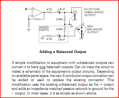
As Joaquin suggests, the impedance-balanced arrangement is the simplest, and does not compromise performance. It's not a cheap solution, it's a brilliant solution.
 
abbey road d enfer said:
As Joaquin suggests, the impedance-balanced arrangement is the simplest, and does not compromise performance. It's not a cheap solution, it's a brilliant solution.

I haven't said is a cheap solution, I've said it is cheap, because it is, it eliminates a gain stage and a few components related to it, but I agree with you it's a brilliant one and is the one I use the most, I think if I don't go for a transformer I'd just rather go for this, I don't think the more complex solutions worth the effort, floating with 3 opamps or some magic IC which does more or less the same, I just don't buy it.

I'll look for those discussions, about the input topology, I don't remember being around on one of those... I've tried the boot strapped input amp and it's hard to measure the CMRR of some slightly unbalanced loads, and still a very good CMRR (~30dB IIRC) if only one input is connected, compared to this scheme where only 6dB are archived in that case. It does a difference in a rough environment, probably it doesn't worth either in a nice environment and not such a big difference from a well designed instrumentation amplifier with one less opamp. I find for nice environments sometimes is enough with the single opamp balanced input, which has unbalanced normal mode impedance but balanced common mode impedance, so decent CMRR is archived and the same 6dB when only one input is used.

JS
 
Thanks for explanations!But it's hard to understand for me because of my poor English.I'm still trying to understand.I will go step by step.

joaquins ,you mean something like this?

irtWp.png


joaquins said:
abbey road d enfer said:
As Joaquin suggests, the impedance-balanced arrangement is the simplest, and does not compromise performance. It's not a cheap solution, it's a brilliant solution.
I haven't said is a cheap solution, I've said it is cheap, because it is, it eliminates a gain stage and a few components related to it,
My comment was not negative, in fact I had not noticed your comment about being "cheaper". I just meant that quite often people call it cheap derisorily just in view of its simplicity. I'm not always an advocate of "the simpler the better", but in this case one would be hard pressed to find any single argument in defavour of this arrangement.
  I think if I don't go for a transformer I'd just rather go for this, I don't think the more complex solutions worth the effort, floating with 3 opamps or some magic IC which does more or less the same, I just don't buy it.
Personally, I don't like transformers, except when galvanic isolation is required. I've toyed with all sorts of variations around the cross-coupled scheme but since the invention of THAT 1646, I've never looked back.
I'll look for those discussions, about the input topology, I don't remember being around on one of those... I've tried the boot strapped input amp and it's hard to measure the CMRR of some slightly unbalanced loads, and still a very good CMRR (~30dB IIRC) if only one input is connected, compared to this scheme where only 6dB are archived in that case. It does a difference in a rough environment, probably it doesn't worth either in a nice environment and not such a big difference from a well designed instrumentation amplifier with one less opamp. I find for nice environments sometimes is enough with the single opamp balanced input, which has unbalanced normal mode impedance but balanced common mode impedance, so decent CMRR is archived and the same 6dB when only one input is used.
Indeed there are many perfectly usable solutions, but they all rely on perfect resistor matching (or trimming), which strongly advocates the use of dedicated chips and again the THAT 1240 series makes it si simple.
 
Matador said:
ForthMonkey said:
joaquins ,you mean something like this?

Yes.  I have switched over to simple impedance balanced outputs in lieu of fancy balancing IC's:  I was shocked at how simple and effective it was.

I will try.For now i have no idea about this design.

But what about THAT design?
 
ForthMonkey said:
Thanks for explanations!But it's hard to understand for me because of my poor English.I'm still trying to understand.I will go step by step.

joaquins ,you mean something like this?

irtWp.png

That's exactly it, if you can provide low DC output you could get rid the caps and the two 100k resistors. A servo isn't the best way of getting to the outside world but I rather prefer not to use caps just because the ones I can find easily are so crappy.

abbey road d enfer said:
Personally, I don't like transformers, except when galvanic isolation is required. I've toyed with all sorts of variations around the cross-coupled scheme but since the invention of THAT 1646, I've never looked back.
For rough environments there is a clear advantage for the transformers, as you said galvanic isolation is one of those, others are archived by the THAT configuration but I have two things about those, one is they are expensive and no so easy to get for me, the second is that I do like simpler path, when possible without compromising performance. I think that's the case for the simpler impedance balanced output with excellent performance and as simple as it can get, you just use your last gain stage you already have and with few other components is ready to hit the outside world. Could be just two resistors which could have inductors in parallel, if the offset is low enough because of a servo or a low offset gain stage depending on the opamp and configuration, if not 2 more caps and 2 more resistors and you are ready to go. As you said I never found anything wrong with that configuration, the only limitations are the 6dB lower signal and noise, so, who cares, and the lacking of floating  output but they are usually not a problem and for fully floating you need a transformer since a IC solution will have a limitation on the CM range it can handle. 

JS
 
OK! Adding resistor to COLD pin is balancing impedance.

Now i added output circuit to first post.Normally output impedance less than 100ohm.So what now?It has balanced output with low impedance,right?

What should i do if i want to get 10K?
 
ForthMonkey said:
OK! Adding resistor to COLD pin is balancing impedance.

Now i added output circuit to first post.Normally output impedance less than 100ohm.So what now?It has balanced output with low impedance,right?

What should i do if i want to get 10K?

That doesn't look right:  the 47R resistor shouldn't be in parallel with the cap, otherwise DC offset will go directly to the output pins.

If you aren't worried about DC offset, the output cap isn't needed at all.
 
Matador said:
ForthMonkey said:
OK! Adding resistor to COLD pin is balancing impedance.

Now i added output circuit to first post.Normally output impedance less than 100ohm.So what now?It has balanced output with low impedance,right?

What should i do if i want to get 10K?

That doesn't look right:  the 47R resistor shouldn't be in parallel with the cap, otherwise DC offset will go directly to the output pins.

If you aren't worried about DC offset, the output cap isn't needed at all.

Thanks.

Let's remove cap...Now 47R goes directly to PIN2 and other 47R goes to GND from PIN3.So?

It has low impedance ouput.But i need high impedance.How can i change impedance?
 
Nothing, that's it, you probably don't want 10k output impedance, that's the input impedance of the following stage, you probably want 100Ω output impedance and 10k input impedance to get a bridging interface. Don't mix them up!
You connect a low output impedance to a high input impedance and you get low voltage losses which is what you want now days, in the old days 600Ω did used 600Ω output and 600Ω input to get matching impedance for best power transference, not we are fine with voltage since power is much cheaper now days.

JS
 
Where are you using the trimpot and how?

If it's at your input as a level control it's just fine, you shouldn't use it at the output and your input receiver should be balanced to get advantage of this configuration.

JS
 
Back
Top