xeawr
Well-known member
Dear fellows,
this is an epic moment in my life: This is the first time that I dare to actually post something online, asking a smart guy or two, to have a look at this schematic. Unfortunately where I live, I don't know anyone thats good with audio electronics, so I'm clueless when it comes to the evaluation of my circuit diagrams.
I spent the last years reading a lot about electronics and spent hours digging through unbelievably comprehensive knowledge bases available online. I had absolutely NO clue about electronics just two years back, but by now I think I know a liiiiiittle bit about this and that - well just enough to get some very (!) basic low-voltage audio stuff done.
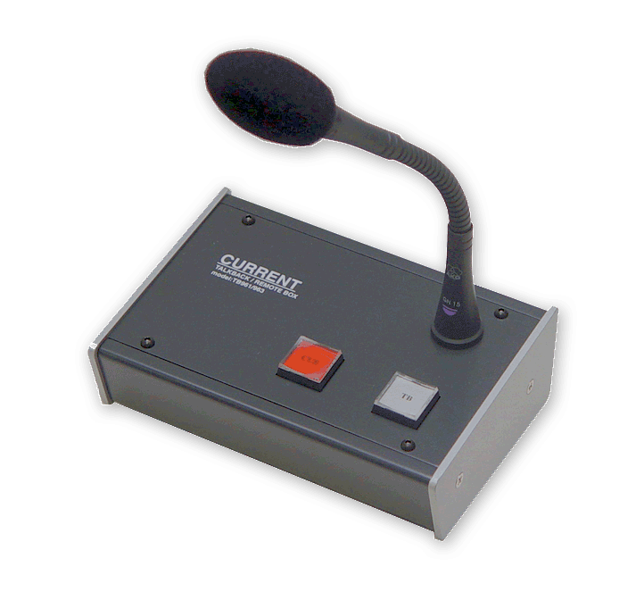
I've drawn a schematic of a Push-To-Talk-Box, which I would use for doing FOH work. As you can see, it is made up of very cheap and readily available parts, yet has some "comfort features" (switchable +48V, LEDs, etc).
Although I conceived this box myself, it is basically a compilation of a number of different schematic that I added into this PTT (Push-To-Talk) schematic (I'll try to post them down there).
As you can tell I struggled with a good looking layout, not knowing if there are any rules where to place what and so on. Please don't mind the mess. Please ask, if there is anything unclear.
May I ask humbly if somebody is willing to quickly have a glance at this and tell me where I have mistakes (before I run off and build it). I've done some breadboarding on parts of it (such as the negative voltage generator), but I don't know if the whole thing makes sense.
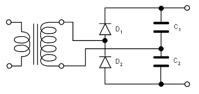
I don't plan to amplify the signal a lot, maybe somewhere between 6-12 dB, just enough, so the mic preamp in the next stage needs only a comfortable amount of gain. I know I'm missing half a volt on the negative supply rail of the opamps: I'll either drop some voltage with a diode, or I'll add two simple zener diode (+ resistor) regulators.
Do I have to worry about this 0.5V offset?
Thanks A LOT in advance for your help!!!


