Reamp Box Not Performing As Well As It Should...

GroupDIY Audio Forum

Help Support GroupDIY Audio Forum:

This site may earn a commission from merchant affiliate links, including eBay, Amazon, and others.

Lumberjack

Member
Joined
Jun 17, 2024
Messages
22
Location
Europe
I recently received a finished reamp box centered around the Jensen JT-11P-1 transformer and based on this schematic:

https://www.jensen-transformers.com/wp-content/uploads/2014/08/as092.pdf

Now that I tested it in a recording setup for Neural Amp Modeler (machine learning based capture system for guitar amps/pedals) clips, the NAM trainer informed me that the replication ESR (error number) is 5.41 and usually only 0.01 and less is acceptable. I never had a problem with my way cheaper Palmer reamp box, so I'm a bit stunned to see that a transformer that costs more than the palmer daccapo, is performing this badly.

I can only assume that the transformer itself isn't the problem as it's in a rugged metal housing and the Jensen quality control can't be this bad when it comes to one of their premium transformers.

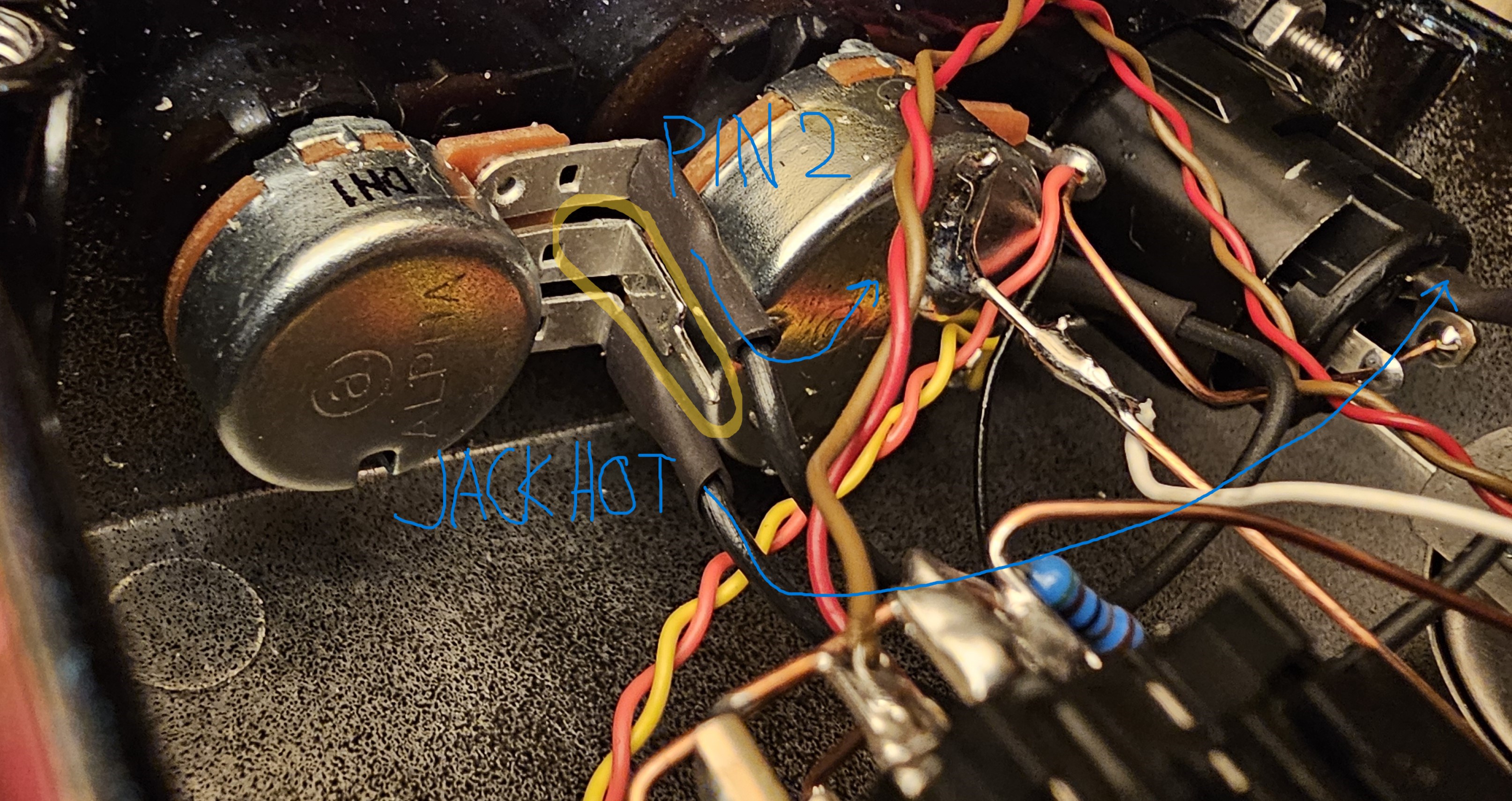
Can anybody please confirm if the wiring is correct and congruent with the schematic above?

Here's the album with pictures of the internal wiring:


The input jack is a 1/4" TRS/XLR combo connector and the output jack is a TSR locking chassic jack (though it's meant to be used with a TS cable):
https://www.parts-express.com/Neutrik-NJ3FP6C-BAG-1-4-Locking-Chassis-Jack-Black-092-084

Apart from that, there's only the transformer and a ground lift switch.

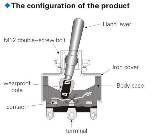
I have one question in particular regarding the SPDT switch that was used for the ground lift in the schematic above. This is the exact switch in question:

https://www.parts-express.com/SPDT-Mini-Toggle-Switch-060-335?quantity=1

And here's a picture of the switch in my pedal:

Gd0HNHd.jpeg


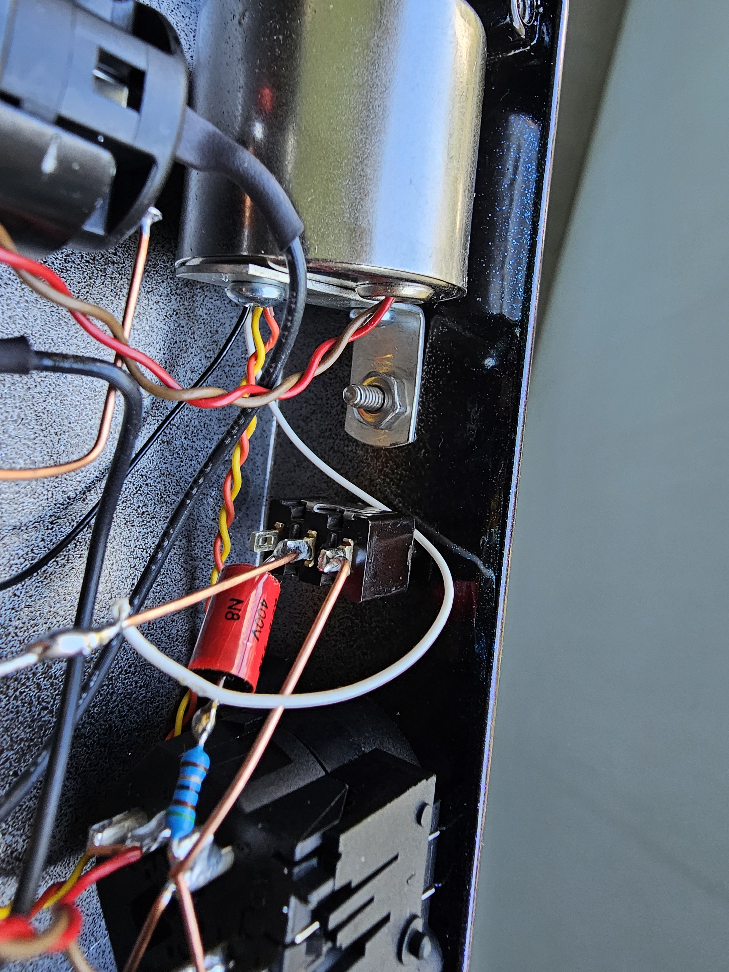
Is the wiring correct on that switch and should the pin that's most closest to the enclosure top remain unused? Is the middle pin that has the RC network connected to it always active no matter if the ground is lifted or not? Is it the wrong switch to begin with for this sort of task?

Is something off with the grounding paths?

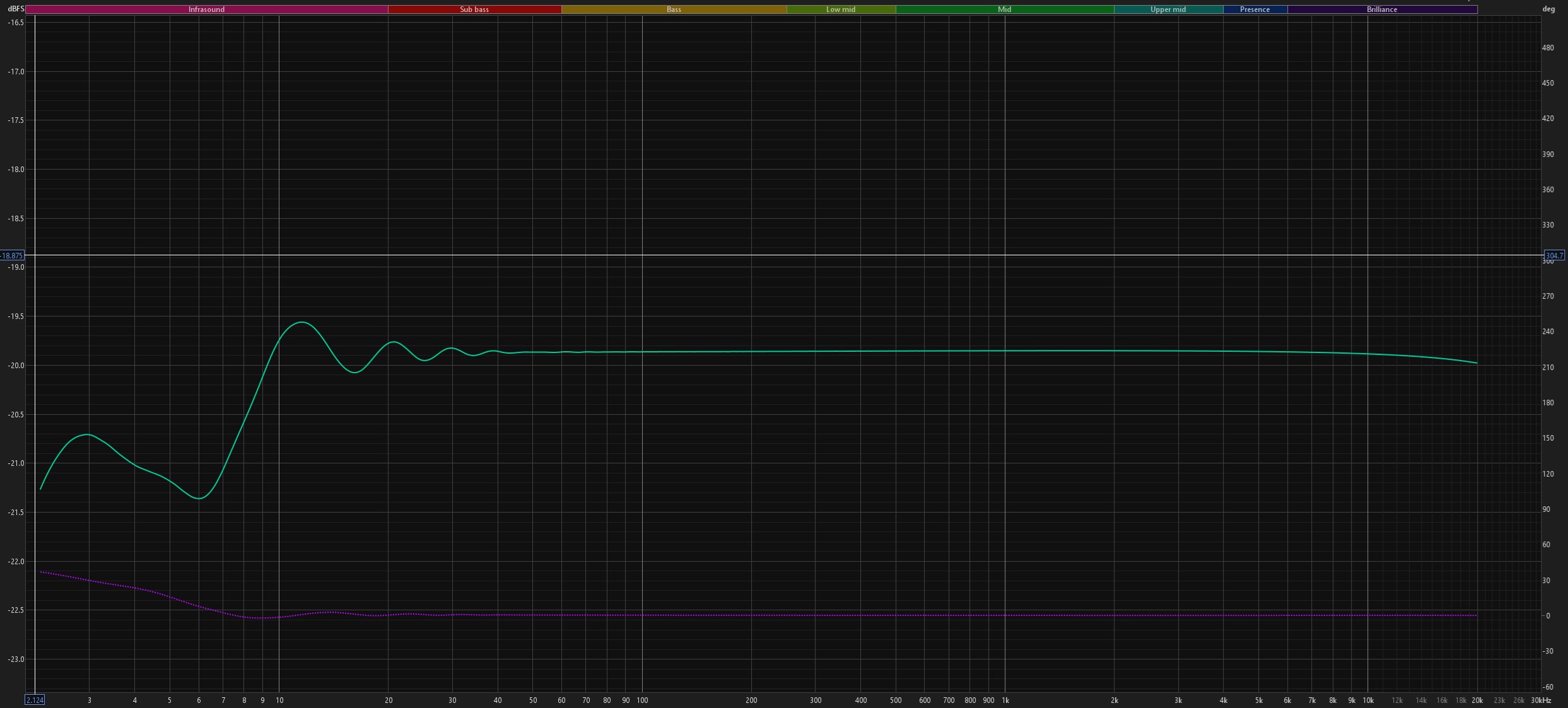
I really don't know where this inconsistency might come from... I also did a Null Test against the Palmer and the Palmer performed about 6dB better and its by no means a premium product...
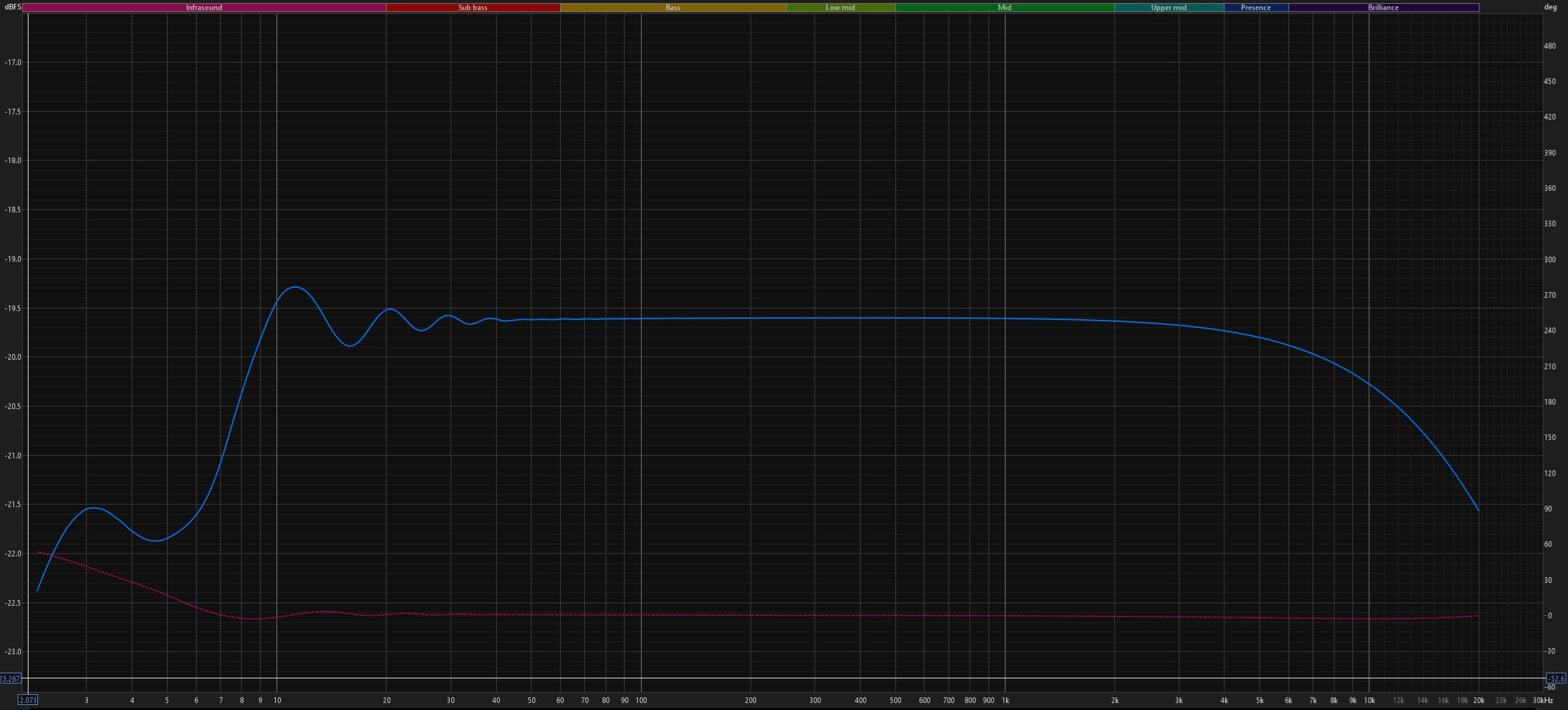
 
Is that just an overall level difference? Or are the frequency responses different? A loopback sweep with RoomEQ Wizard could show some things...
The Null Test looked like this:

I played my guitar directly into the Hi-Z input of my audio interface and recorded it. I then routed that signal via line out (100 Ohm balanced TRS) consecutively into the two reamp boxes.

I then aligned each reamp box output clip sample accurately to the DI track and level matched both of them to the DI track down to 0.01 dB accuracy.

The Palmer's getting -44.5 dB in the Null Test (after I phase flip the DI track and play both the palmer and DI track simultaneously) and the Jensen's getting -38.4 dB, so quite a bit worse.

The frequency graphs that I did with REW do not reflect that however at all, the Jensen should actually come out on top or at least equal the Palmer in the null test.

Here's the Jensen with volume pot set to about 60% and impedance pot all the way off:

gJipTn0.jpeg


This is what the Palmer looks like in comparison with volume at 60%:

X6H1dZv.jpeg


As you can see, the Palmer has a gradual 2 dB total roll-off after 2k, the Jensen's roll-off is around 0.1 dB, so the Jensen should act more linearly.

Although, if I set the impedance pot to the max on the Jensen reamp box, I get this plot:

cE3CVDU.jpeg


But since I don't have to set it this high, I see no reason why it shouldn't work with the more linear setting of keeping the impedance knob fully off.

Just to get back to the SPDT ground lift switch. It should work like this AFAIK:

wyRnmib.jpeg


Wouldn't this mean that the middle position is always in contact and only the out pins get to make the difference? In the Jensen reamp box, the RC network is connected to that middle pin. Would this possibly cause the inconsistent behavior during recording/null test?

Also, the neutrick locking jack is actually deviced for TRS cables with Tip, Ring and Sleeve terminals. This reamp box has the sleeve and ring connected to the same copper wire. I assume that's the way it needs to be if I do plan to only use TS/instrument cables on that jack?

Is there anything else that I could check to see why it's behaving this weirdly?

I want the Jensen to work, I just don't know what's going on here. For the first time I actually had to deal with error messages that I never got before during the NAM training process etc., and they disappear once I get back to using the Palmer...
 
I have a few questions:

1. Do you really need a reamp box for this? Impedance from your interface to and amp is no problem and you can lower the output level of your DAW track to suit the amp. I use reamp boxes only if they have features I desire, like filters or tone controls or ground lifts, etc…

2. Do you want “purity” for reamping? The whole point of realping is to simulate the effect of a guitar amp (or whatever) on a signal. It’s an effect with lots of tonal options as it is- the remap box is probably the least influential on the sound.

3. Is there something you hope to achieve with a transformer instead of the electronic reamp?

A null test in this case seems like the wrong test- you should decide if you can achieve the reamp effect you like with either box.

Many people would even wholly question the use of a “synthesized” guitar amp, but that’s your artistic choice.

I say go and make some music with your guitar- not measurements.
 
1. Do you really need a reamp box for this? Impedance from your interface to and amp is no problem and you can lower the output level of your DAW track to suit the amp. I use reamp boxes only if they have features I desire, like filters or tone controls or ground lifts, etc…
I tried to use the line out directly into my Marshall JMP which has an input impedance rating of 1 Megaohm and the sound was too noisy and bright, not at all similar to when going into the amp with a guitar. I do need it at least for a ground lift but primarily to get the amp to react as close as possible as it does when going straight in with the guitar.

2. Do you want “purity” for reamping? The whole point of realping is to simulate the effect of a guitar amp (or whatever) on a signal. It’s an effect with lots of tonal options as it is- the remap box is probably the least influential on the sound.
We guitarists are a picky bunch. There will always be a difference between going straight into the amp with a guitar versus reamping that same guitar through the DAW into the amp afterwards, but I'd like to keep that difference as small as possible. There is a noticeable difference between different reamp boxes, at least between the three that I have there is a noticeable difference.

3. Is there something you hope to achieve with a transformer instead of the electronic reamp?
I want to create NAM captures, basically capturing my amp at a specific setting in a digital machine learning based capture. It's quite close to the real thing if the real thing isn't available.

3. Is there something you hope to achieve with a transformer instead of the electronic reamp?
That's what all the NAM capture creators use and some of them are experienced guys who own mixing studios etc., so there must be a reason why even the pros turn to reamp boxes in those instances.

I would make some music and just capture the amps without going into the technical details.

It's just that this reamp box does something the other two boxes don't and it gives me errors in the NAM training process. It makes no sense that a much more expensive device is giving me subpar, unusable results, while 80 bucks units do well with the same amps, same signal chains etc. and I want to find out why that is and what's wrong with it...
 
I tried to use the line out directly into my Marshall JMP which has an input impedance rating of 1 Megaohm and the sound was too noisy and bright, not at all similar to when going into the amp with a guitar.

Chuck a 10k in series with the input to simulate some source impedance..?
 
the NAM trainer informed me that the replication ESR (error number) is 5.41 and usually only 0.01 and less is acceptable.

So far nothing in the measurements you have shown stands out as obviously wrong. You will likely have to dig into either documentation or code of NAM to find out what "ESR" really means and how it is determined.

Wouldn't this mean that the middle position is always in contact and only the out pins get to make the difference?

Yes. That matches the Jensen schematic you linked.

This reamp box has the sleeve and ring connected to the same copper wire.

That is correct. It won't really matter much, on a TS plug the ring contact lands on the plug sleeve, so the plug will connect the R and S contacts of the connector together anyway.

Is there anything else that I could check to see why it's behaving this weirdly?

I don't think other people will be able to help much until you narrow down what "weirdly" means in this context.

I then aligned each reamp box output clip sample accurately to the DI track

How accurately? It would not take very much misalignment to get a 10dB difference in higher frequencies. Although given the high frequency roll-off of the Palmer box that makes me think that the measurement cannot be weighting high frequencies very much in the ESR result.

Is ESR measured in a way similar to the null test you described? Guitar straight into DI, then recorded signal through re-amp device back into audio interface, and NAM compares the two?
When I search with google I see a lot of references to ESR, but have not found a concise definition and methodology yet.
What I have found seems to imply in context that ESR refers to the amp model error ratio, compared to the signal from the actual amp.
 
So far nothing in the measurements you have shown stands out as obviously wrong. You will likely have to dig into either documentation or code of NAM to find out what "ESR" really means and how it is determined.

How accurately? It would not take very much misalignment to get a 10dB difference in higher frequencies. Although given the high frequency roll-off of the Palmer box that makes me think that the measurement cannot be weighting high frequencies very much in the ESR result.

Is ESR measured in a way similar to the null test you described? Guitar straight into DI, then recorded signal through re-amp device back into audio interface, and NAM compares the two?
When I search with google I see a lot of references to ESR, but have not found a concise definition and methodology yet.
What I have found seems to imply in context that ESR refers to the amp model error ratio, compared to the signal from the actual amp.
First I want to clear up what "weirdly" or "inconsistently" means in this context.

The NAM profiler wants to receive a well-behaved amp response so that it can use machine learning to train a capture on it. There needs to be some predictability, though, in order for the machine learning to function. If I send a signal "xyz" into my amp it can give me "xcbjulu" back, it's important that it always gives me that "xcbjulu" back if I feed it "xyz". With my cheaper reamp boxes, this is still the case, with the new Jensen, not so much. I'll illustrate it further with this picture:

HUVvuRA.jpeg


The two blue columns at the beginning and end of the test signal are basically Dirac impulses. The amp response below is how the amp reacts to these impulses. Whenever the Dirac impulse is fed to the amp, it needs to produce the same response ideally. It's not the quality of the response itself, it just needs to be repeatable and it needs to resemble itself. Above you can see what a healthy amp response is, two times an identical signal as a response to the same input signal.

In a way, we're checking if the amp behaves like an injective function. I want f(x) to always deliver 23445098 and f(y) to always deliver 4568881 etc. There can be some variation, as indicated by the ESR number which measures the deviation between these two responses that in theory should be identical. Normal devaitions are below 0.01 and for clips that I generate with the Jensen reamp box, these numbers are above 5.0, so clearly something's awry.

The Null Test is just further proof that the box is performing below its capabalities somehow.

And yes, I did the Null Test very meticulously, the samples were aligned down to a single sample of precision, with maximum zoom in my Studio One DAW and the level has been matched down to 0.01 dB, so there shouldn't be a 6dB difference between jensen and the way cheaper reamp boxes...

This is what the error message looks like:
nsBtOgg.jpeg


I redid another capture and it lead to the very same results.

I did notice that in the up position of the ground switch, the ESR is slightly lower, by 0.5, but still way higher than 0.01.

Is in my case the ground lift engaged when the switch is in the up position (when the switch points to the enclosure top)?

And no, I think I'll stick to reamp boxes. John Cuniberti already did it this way in the 80's with Joe Satriani in the studio and there's a reason why decades afterwards people still use transformer based reamp boxes to achieve the same goals, even the biggest recording studios to that.
 
Can this be a possible source of irregularity? The middle pin of the impedance potentiometer is not connected to anything, but in the schematic above, the hot jack signal is connected to both an outer pin and the middle pin. Here's what it looks:

ktDd6fT.jpeg


The jack connection is correct as is the connection to the volume pot, but the middle pin is left untouched...
 
The middle pin of the impedance potentiometer is not connected to anything

That would be the equivalent of having a fixed resistor inserted in the output, but that does not match the measurements you posted earlier showing a change in frequency response when you changed the impedance pot from min to max. Could you have made a mistake and that frequency response change was from changing the level pot? Or the level pot is the one which is miswired?

The error message says that signal chain too noisy is a possible cause. How is the noise level when you listen? Is there a lot of hum?
 
You showed a graph that indicates the impedance pot is working. So maybe the centre pin is connected to one side with a jumper you cant see.
The Jensen is working and has better frequency response than the Palmer. But you clearly like the sound of that rolloff. So go with that, start making music, and be happy. You can now sell the Jensen box and get your money back.
 
Well that definitely can't be right, the pot then doesn't do anything...
I didn't see that the middle lug was indeed connected to the lug below it that receives the hot signal from the jack. It was just a little wire barely noticeable soldered unto the two lugs from the other side, so there's continuity between these two lugs and the impedance pot does seem to work as intended. The frequency response graphs are further proof that this is indeed the case. Sorry for the false alarm!
That would be the equivalent of having a fixed resistor inserted in the output, but that does not match the measurements you posted earlier showing a change in frequency response when you changed the impedance pot from min to max. Could you have made a mistake and that frequency response change was from changing the level pot? Or the level pot is the one which is miswired?

The error message says that signal chain too noisy is a possible cause. How is the noise level when you listen? Is there a lot of hum?
I've traced the culprit that's causing way too high ESR numberrs down to the new reamp box. The exact same setup with the same settings and levels, just with a different reamp box, has an ESR of only 0.0008. Once I use the Jensen reamp box instead and leave everything else as is that number becomes greater than 5.0... it has nothing to do with a high noise floor (which isn't the case anyway), failing tube amps or changing settings on the fly, it's all down to the new reamp box 100%.
You showed a graph that indicates the impedance pot is working. So maybe the centre pin is connected to one side with a jumper you cant see.
The Jensen is working and has better frequency response than the Palmer. But you clearly like the sound of that rolloff. So go with that, start making music, and be happy. You can now sell the Jensen box and get your money back.
The Jensen does show a better frequency response and I'd like to use it instead of the cheaper alternatives, however, as I've outlined above, the recorded files that I get with the Jensen reamp box are simply rejected by the NAM trainer whereas those made with a cheaper, less accurate reamp box are strangely accepted by a wide margin. This is not due to the quality of the recorded tracks or the frequency response, it's due to inconsistency.

Two same signals are sent to the amp once in the beginning and once in the end of the training clip. If the amp doesn't respond to those identical signals in an almost identical fashion, there's too much variance and inconsistency that it simply becomes unusable for machine learning based training.

I'm just trying to find out why that is so and if there is an underlying explanation found in the wiring, grounding etc. of the reamp box itself.

And I'm not trying to sell Jensen reamp boxes anyway, I just want to use this one for myself with usable results.
 
Last edited:
Well I had a look at the NAM trainer, and none of it makes sense. So you record a guitar, and then play that into the trainer? The guitar has nothing to do with how the amp sounds. they are two different things. And the concept that you are going to exactly model two guitar amps makes no sense at all. Others have tried it, and depending on their abilty to impress with bullshit, has enabled them to sell product. If you want the sound of a Marshall, buy a Marshall. Thats it.
 
Well I had a look at the NAM trainer, and none of it makes sense. So you record a guitar, and then play that into the trainer? The guitar has nothing to do with how the amp sounds. they are two different things. And the concept that you are going to exactly model two guitar amps makes no sense at all. Others have tried it, and depending on their abilty to impress with bullshit, has enabled them to sell product. If you want the sound of a Marshall, buy a Marshall. Thats it.
No, that's not it, at all. Just completely wrong.

I've talked about this process in post #10: https://groupdiy.com/threads/reamp-box-not-performing-as-well-as-it-should.88120/post-1160199

The trainer needs two files: A test signal that gets fed into the amp and the recorded response of the amp to this input track. You do this entirely in the DAW, no NAM trainer involved. These two files get exported from the DAW and get fed into the trainer later on.

The training is then nothing more than correctly figuring out "if test signal does this" then "amp does that" and find a model/capture that does this assignment most accurately.

Before the training begins, the output file of the amp gets checked for consistency and noise levels. If it fails this basic check, then no training is possible. The amp can sound awful, but if it's consistent in its response, it can be used for training because it behaves normally instead of erratically and all over the place.

When you play an A chord two times with the same intensity and technique into the same amp with the same settings and setup, you expect it to sound extremely similar. This test does nothing else but the check happens with Dirac impulses instead of A chords.

Let's say the test signal does "AB" and I get "145" the first time around, later on it does "AB" again, but this time, I get "245" out of the amp signal. That's unusable. The model needs "AB" to always produce either "145" or "245" during the same recording process, otherwise, the amp doesn't sound like itself consistently. That's the case with this Jensen reamp box and it never happened with the cheaper alternatives.

Here's the graphical illustration:
cc48b17f9d127d695538c1e5b19989f7.jpeg
 
So do you have to have the amp you want to model and put a test signal through that amp? Where do you get the test signal? How does the modeller know what amp it is from?
 
So do you have to have the amp you want to model and put a test signal through that amp? Where do you get the test signal? How does the modeller know what amp it is from?

The test signal can be downloaded here:


You put this file into your DAW and then you route it via line out into your real amp and cab/mic or reactive load and back into your audio interface and ultimately DAW. The signal path in my case looks like this:

DAW test signal -> Line Out (100 ohm balanced) -> TRS/TRS cable -> Reamp Box -> TS/TS cable -> Real Amp -> Reactive Load -> Hi-Z Input -> DAW

Once it's recorded inside the DAW, I need to align it to the test signal and trim its length so that it's equally as long as the test signal.

Then you can feed the test signal and this output signal into the NAM trainer and then it does its thing to create a capture of the amp at that particular setting.

However, as I mentioned above, the trainer imposes a basic check regarding noise level and consistency. If this basic check is unsuccessful, then it's best not to start the training at all. That's unfortunately the case with this new reamp box.

The modeler or NAM trainer doesn't need to know the amp or its circuit type, tube types etc., it's a black box approach that only needs the test signal and the output signal that is created by playing the test signal through the audio hardware of your choice. It doesn't matter if it's an old tube or solid state amp, a preamp from an SSL desk, an API compressor or a Boss distortion pedal. It will train anyting so long as it delivers a reasonable and predictable response to the test signal.
 

Latest posts

Back
Top