REDDI DI

GroupDIY Audio Forum

Help Support GroupDIY Audio Forum:

This site may earn a commission from merchant affiliate links, including eBay, Amazon, and others.
dmp said:
The 1K pot on as the output level does not look right. Maybe it should be a voltage divider and go to ground?

Maybe I got it all wrong, but I thought of it more as a load-regulator for distortion-control. If distortion is reasonable for passive bass-pickups without the 1k pot I wo'nt use that in the final design. Less is less.
 
I think you meant the input pot to be 1Meg not 10. The 1K pot should be wired across the transformer secondary as a pot divider.

You can use my poor man's tube gain make up PCB to build the SRPP. In the spirit of Christmas I am happy to donate 10 of these PCBs to builders of this project.

Cheers

Ian
 
ruffrecords said:
I think you meant the input pot to be 1Meg not 10. The 1K pot should be wired across the transformer secondary as a pot divider.

You can use my poor man's tube gain make up PCB to build the SRPP. In the spirit of Christmas I am happy to donate 10 of these PCBs to builders of this project.

Cheers

Ian

I'd love to have a go at building a valve DI Ian!  ::)
Chris
 
ChrisPbass said:
ruffrecords said:
I think you meant the input pot to be 1Meg not 10. The 1K pot should be wired across the transformer secondary as a pot divider.

You can use my poor man's tube gain make up PCB to build the SRPP. In the spirit of Christmas I am happy to donate 10 of these PCBs to builders of this project.

Cheers

Ian


I'd love to have a go at building a valve DI Ian!  ::)
Chris


OK Chris, one PCB is reserved for you. 9 left.

Cheers

Ian
 
Hi Ian,would you kindly send one to me as well.Also at the same time i'll put in an order for a few other boards.
I'll send you a pm in the new year.Tks
 
lotus said:
Hi Ian,would you kindly send one to me as well.Also at the same time i'll put in an order for a few other boards.
I'll send you a pm in the new year.Tks

No problem. My pleasure.

Happy New Year

Ian
 
Hi

I'm building a DI based on the 6N1P.
But I've some question about the ouput impedance and transformer.

B+ is 240v.

So, calculating the ouput impedance is :
(Rp * Ra) / (Rp + Ra) => (150 * 4.4) / (150 + 4.4) = 4.27K

Is it right? but is it not too small for the ouput impedance?

And another, I don't put a load resistor, do you think I need to put one?

Thank's to all !


Attachments

  • TubeDI.png
    TubeDI.png
    8.9 KB
drask said:
Hi

I'm building a DI based on the 6N1P.
But I've some question about the ouput impedance and transformer.

B+ is 240v.

So, calculating the ouput impedance is :
(Rp * Ra) / (Rp + Ra) => (150 * 4.4) / (150 + 4.4) = 4.27K

Is it right? but is it not too small for the ouput impedance?

And another, I don't put a load resistor, do you think I need to put one?

Thank's to all !

With a 150k Rp your plate current will be in the region of 1mA or so. At this current the tube's ra will be much higher than 4.4k. Also, the cathode bias resistor is not bypassed so the effective ra is increased by the cathode resistor * mu or about 90k. Your small signal output impedance is therefore in the region of  60k.

Small signal output impedance is not a good indicator of drive capability; for that you need current as well and you have very little plate current.

I would suggest you redesign the output stage for an idle current of about 10mA and bypass the cathode resistor. This will give you an output impedance much closer to the value you calculated and enough current for reasonable drive capability.

Cheers

Ian
 
Hello all,

I've been speaking to the ever generous and ever knowledgeable ruffrecords via email.  The following schematic has been arrived upon (suggested by ruffrecords  ;) ).  Things to note are the tube type (6922) and transformer type (VTB2291).

I am currently creating a wiring diagram to show connections when using Ian's (ruffrecord's) PSU board and poorman's tube gain make-up.

I'm looking forward to making one/two of these!


Attachments

  • SRPP DI - 9622 version.png
    SRPP DI - 9622 version.png
    33.5 KB
Hi,

I drew a tube DI too, following the advice of ruffrecords too.
I based mine on a 6N1P.

I'll be curious to compare the sound of the two different design and tube.
Irfrench, if you build it, please post your sound demo here :)
 
Awww shucks, now you've gone and done it. 

I'll HAVE to build one now!  ;) ;D ;D

I'll be sure to record samples with it, probably bass (original huh?) as I'd like to compare it to a couple of other DI's too.

Ian (Ruffrecords) is a pleasure to speak to, and seemingly has an infinite reserve of patience.  A real Gent.


Anyway, I'll hopefully get on to it soon.  Will you be posting your schematic?

Cheers,
Ian
 
This will be very interesting comparison. A lot of EBay sellers try to make out the 6N1P is the same as the 6DJ6/ECC88/E88CC/6922. My own tests have shown conclusively that they are not. In general they are noisier and have greater distortion. If you want a real Russian equivalent to the 6922 and friends the 6HN23 is the one to go for. They are quite cheap and perform almost as well as the best 6922s.

I tend to think of the 6N1P as the dirty little brother of the 6922 so in this application I expect it could create an interesting sound especially on bass.

Cheers

Ian
 
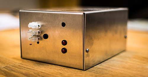
I am crap at mechanics so I am always on the lookout for ready made enclosures that give give projects a professional finish. So, does anyone know if there is an off the shelf enclosure like the one used by the REDDI?

Cheers

Ian
 
I'm guessing the closest will be a valve mic PSU case?

I'm probably going to rack a pair of these up so haven't thought about it, but the first/proto will be done reusing an ugly ol' Maplin(gasp!) enclosure:

tumblr_inline_mh5jnyeRHm1r2bfgn.jpg


Thanks for all your help,
Ian
 
I'm going to use the PSU case from Dan at Collective Cases ($85)


Attachments

  • Side_XLR_tube_mic_PSU.jpg
    Side_XLR_tube_mic_PSU.jpg
    256.5 KB
Yup.  Those are the ones.  Beautiful.


http://www.groupdiy.com/index.php?topic=41963.msg618199#msg618199


In all honesty, now I've seen Dan does a stereo case  I'm thinking I may sack the rack mount idea off!  ;D ;D

Just get combi XLRs for the input and - bingo!


Ian
 
dmp said:
I'm going to use the PSU case from Dan at Collective Cases ($85)

Yeah, my plan was to be able to use the PSU cases for a number of things like this or a tube preamp case as well.  I suppose I could do a special run of them in a different color if enough guys could agree on it for this project.  Maybe Red?  haha
 
Massive Tease!  ;)

I quite like the grey TBH.

Do you have any pics of the stereo units? I'm wondering where the input and output level pots could/would/should go.

8)
 
Back
Top