Ribbon Resonant Frequency Tunning/Tensioning - Ribbon Microphones

GroupDIY Audio Forum

Help Support GroupDIY Audio Forum:

This site may earn a commission from merchant affiliate links, including eBay, Amazon, and others.
Interestingly in the BBC microphones publication they give only the frequency response of B sample from lab tests in the technical report , the A sample was by far superiour . No wonder it was marked confidential , Beyers own frequency graphs of the mics performance varied quite a bit from the measured results , hard to know if variations in the measurement or method of excitation or ribbon quality are at play .

Maybe we can come up with a test jig that allows REW to measure the impedence curve of the motor at lower frequencies via an injected test signal , then we can easily identify the LF resonance .

https://www.roomeqwizard.com/help/help_en-GB/html/impedancemeasurement.html
Question is how do you adapt it for measurement of a ribbon motor/transformer instead of a loudspeaker
 
Thats an interesting technique Kaltavilla , thanks for letting us know about it.

below is a close up of an M160 , you can see the middle section of the ribbon is made rigid by lenght wise corrugations .
 

Attachments

  • M160 ribbon.JPG
    M160 ribbon.JPG
    45.4 KB
The big old BBC ribbon mic has a ribbon tensioner arrangement also .

I guess it more a 'set and forget' type thing , where after the ribbon has been clamped any attempt to adjust it will most likely result in destruction .

I think the alignment of the ribbon in the gap is do-able by eye ,assuming good tollerances in the cutting of the ribbon itself and some practice . Its not something you want to be poking with feeler gauges in any case .

Pistonic ribbons Id like to learn more about and Im sure the BBC archives will shed plenty of light on the subject . I did try making a ribbon for a Beyer M-130 once from cigarette packet alu foil that I had removed the paper from reverse side , because the foil itself is embossed it was very fragile , the experiment was a failure in the end .

Zig-zag /corrugated , same thing , gear wheels etc
Pistonic is where the ribbon is formed with a rigid structure in the middle , towards the edges there are a few corrugations so the main part of the ribbon moves pistonically in the gap , a corrugated ribbon tends to move in a slightly wobbly way which results in resonances and overshoot /decay artifacts on transients .

I'm just about to get stuck into the BBC ribbon microphones documentation after my coffee ,
The great thing about the BBC docs is the plain language explanations of every aspect of the design/opperation of their stuff , but also including other companies products that they incorporated into their equipment schedual. The Beyer M160 looks like a good place to start to learn more about the pistonic ribbon .

http://www.bbceng.info/ti/non-eqpt/TI_S2_Microphones.pdf
page 114

below is the internal BBC test report on the Beyer M160 that Maric listed , Im just getting into it now ,but it seems to detail methods of frequency response measurements , above 200 hz ,free field room responce ,
and traveling wave tube below 200 hz .

http://downloads.bbc.co.uk/rd/pubs/reports/1965-32.pdf
Ive been making ribbon mics for about a year now and have not had any issues with making ribbons from cigarette packaging. The ribbons end up being 40 microns instead of the 2.5 microns used in commercial products but the 40 micron ribbons are more robust. I use a tool with plastic gears to corrugate the ribbons (Geistnote). I have been hand winding my own torrid transformers and building bodies with my 3D printer. I had to pay extra attention to shielding to control noise, but once I got that under control, my mics perform at about the same level as the MXL mics.
 
The old school way that I learned of was that the resonant freq should be below the threshold of hearing, and has typically been between 8 and 12 Hz.

Kaltavilla,

This is way low for a ribbon. Being a mass controlled system the ribbon turns into stiffness controlled one on low frequencies with fall of response below. Our intuition tells us the corner frequency depends on tuning frequency, which is only one part of it. Another part is air load and viscosity of the air in the slit between the ribbon element itself and magnet/pole pieces. With those in mind the corner frequency usually is between 20Hz and 30Hz, depending on the design (here I assume large geometry ribbons).

Tuning the ribbon anywhere below that range makes its operation inefficient and unstable, with series of horizontal resonances in a quite broad range. Besides, such a ribbon is prone to rubbing pole pieces with its rotation, or side tilt.

Hope it is helpful.

Best, M
 
Last edited:
Hey there,

Whoops asked for my thoughts on this thread (which I'd read in the past, and didn't comment on, as I felt things were fairly well covered).

As has been shown, everyone figures out what works for them. I've tried several of the methods listed here, and they all can work and are valid. It comes down to what process works for you, given your equipment and level of commitment.

For the ShinyBox mics that I built for ~16 years, the production process eventually got dialed in( a couple stumbles early on, which are part of learning), and once there, it just happens with consistency. I still checked the resonant frequency and listened to each mic, and the majority of the time, the tuning was correct. If it wasn't, starting over with a new ribbon is generally the best approach.

There is no substitute for experience in this area, to be honest. You can go in with the most enlightened, intelligent, and thought out plans, but ultimately, this is something that happens between your eyes, hands, and ears, and becomes an exercise in overcoming your own limitations. Forward progress for me has always happened with time, attention to detail, and an eye toward continual improvement.

I feel fortunate to have talked with Marik and other ribbon mic manufacturers over the years. We don't trade secrets so much, but from the conversations, you gain the occasional insight, or something sets off a light bulb for further experiments. With the pandemic, and changes in the pro audio market, I certainly miss those discussions.

In general, the longer the ribbon, the lower the resonant frequency. For the casual mic ribboner, once you take the bow out of the ribbon (maybe the tiniest bit more), that would roughly be a decent place to stop.

Ultimately, your ears are going to be the judge. Sounds good, is good. If you have any doubts, start over and put a new ribbon in. You'll learn something.

Hope this helps in some way

Regards

Jon
 
Last edited:
Kaltavilla,

This is way low for a ribbon. Being a mass controlled system the ribbon turns into stiffness controlled one on low frequencies with fall of response below. Our intuition tells us the corner frequency depends on tuning frequency, which is only one part of it. Another part is air load and viscosity of the air in the slit between the ribbon element itself and magnet/pole pieces. With those in mind the corner frequency usually is between 20Hz and 30Hz, depending on the design (here I assume large geometry ribbons).

Tuning the ribbon anywhere below that range makes its operation inefficient and unstable, with series of horizontal resonances in a quite broad range. Besides, such a ribbon is prone to rubbing pole pieces with its rotation, or side tilt.

Hope it is helpful.

Best, M
You bring up some great points Marik.

Thanks for sharing your insight.

I was merely conveying the technique I learned from some old timers.

It can easily be adjusted to produce a resonant pulse source at any frequency you desire.

This mechanical analog method is an easy cheap way to produce very low frequency pulses.

In the past, it was not so easy for most sound systems to deliver extremely low frequency test signals.
 
Question on ribbon tuning. How do you corrugate the ribbon and keep it straight as it goes through the corrugator? I used a thing I got on ebay but the play of the ribbon through the device makes me waste a bunch of ribbons. I've seen people use legos.

Another question. What does the gap between the ribbon and the magnet produce? Less level, if more gap? Reduced hi end? How do I get more high end when tensioning?
 
Question on ribbon tuning. How do you corrugate the ribbon and keep it straight as it goes through the corrugator?

if you check the above video in the corrugating jig there’s s guide indentation to keep the ribbon straight. Without it it’s hard to corrugated it straight
 
Question on ribbon tuning. How do you corrugate the ribbon and keep it straight as it goes through the corrugator? I used a thing I got on ebay but the play of the ribbon through the device makes me waste a bunch of ribbons.

I was installing a new Ribbon in a chinese mic today, it came stock with a very thick ribbon with huge sagging.

I had to waste 4 Ribbons (cutting a ribbon from a sheet, corrugating and trying to install it) and I was never able to corrugate any of them Straigh, they move a bit in the corrugator so instead of being perfectly straigh they have some curves.
With my corrugation Jig I was never able to corrugate a Ribbon Straight.
What I do is I cut a very long Ribbon, more than 2 times the lenght I need and then after corrugation I choose the "most" straight part to install in the mic.
It's hard work and to succeed in installing 1 ribbon I normally waste 4 to 8 ribbons.

This is my Corrugation setup, it's called "Paplin paper Crimping Tool"

Screen Shot 2022-09-02 at 03.32.08.png

I really would love to get something better,
a crimping jig with a guide so the Ribbon is Straight after being corrugated.
Please if anyone has one to sell or know where I could buy one please let me know.

Thanks
 
Another question. What does the gap between the ribbon and the magnet produce? Less level, if more gap? Reduced hi end? How do I get more high end when tensioning?

Marik wrote in post 8
"The tighter gap you can achieve the better lower end response you get."

As for high end I don't think you get more High End when tensioning,
tension will affect more the Low End response and how low will it go.
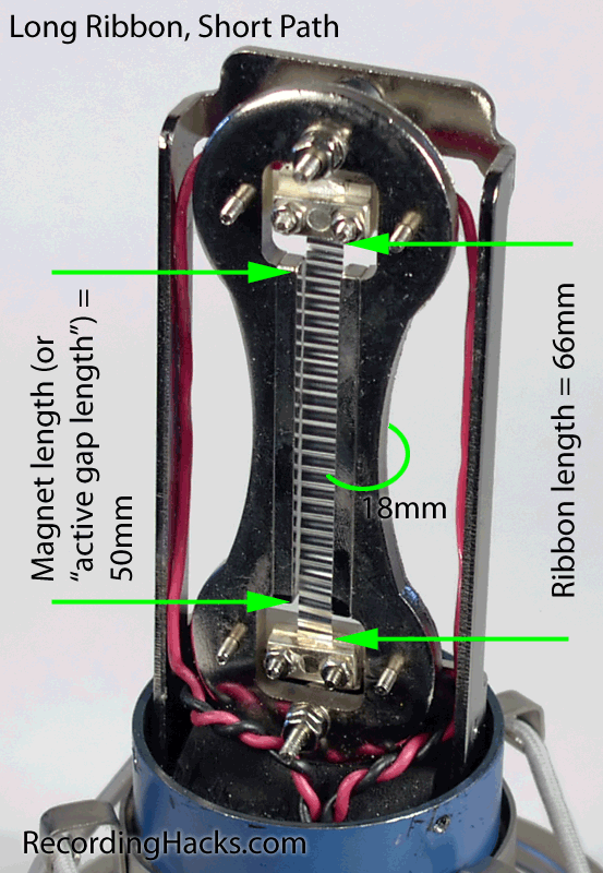
High end in Ribbon Mics has to do with the distance the air travels around the magnets from front to back.
That's why some motors are designed to be thinner on the sides,
check this example, the distance marked as 18mm will affect the high end response and extension

long-short_lg.png
 
Here is the process of making and installing ribbon which should help you to get into ballpark. First, with .001" graduation calipers measure the gap. Then pre-cut ribbon leaving some 0.010"--0.020" pole to ribbon gap per side (say, if the gap is .200" then make the ribbon width 0.196"--0.198"). The tighter gap you can achieve the better lower end response you get.

Hi Marik,
I tried today all your great suggestions/advice in post 8.
Unfortunately with my manual methods and primitive tools it's impossible for me to have such a small pole to ribbon gap, I need to cut the Ribbon much Thinner than what you suggested (the ideal size and gap).
What I find is that for a .200" gap size I need to cut the ribbon at around 0,160 and not 0.196.
It has to do with 2 factors, first one is that I'm not able to corrugate the Ribbon perfectly straight, it comes out of the corrugation rig with some slight curves.
And then as I install the Ribbon by hand if it's too tight inside the gap it's really dificult for me to install it, it keeps wanting to touch the magnet and at some point things get messy and it breaks after moving back and forth while trying to make it straight and relaxed in the gap.

Well I'm just an amateur DIYer, but would love to improve a little big skills, at least to be able to replace the thick and saggy ribbons in Chinese mics.

By the way, I was able to replace a ribbon today in a Chinese mic (very thick and big sag) for a 1.8 micron and the sound improved considerably.


Thank you so much Marik for sharing and for your advice
 
on side note: have someone cutted the ribbon with laser? it is possible? I think I saw somewhere that Royer does it that way? I would imagine it would melt the edges as it is so thin. it would maybe hardened the edge.
 
@ whoops
are you using rubbing alcohol when handling ribbon? it may help adhere to the gear to maintain a straight feed
 
@ whoops
are you using rubbing alcohol when handling ribbon? it may help adhere to the gear to maintain a straight feed

I use alchool to it adheres to one side of the ribbon motor when I'm mounting it inside the gap.
As for the gears, the ribbon gets corrugated sandwiched between 2 papers, RCA style and not direct corrugation like with the Royer Jig.

With the jig it will never be corrugated straigh, with alchool or not, direct or sandwish, it doesnt matter, it's not a proper jig, it works but it's not good
 
maybe the gears could be more co-planar--
what if you put an elastic strap/belt/rubberband around the pair of gears to reduce eccentric rotation
 
Are you feeding ribbons through with the crimper positioned that way? You might have more luck with getting a straight crimp if one of the short ends of the block is against the table, and then you feed it through. Gears perpendicular to current position basically.

You might like these:
https://www.tubewringer.com/?v=a284e24d5f46
 
I might build something in the future using these gears, something with a guide for the ribbon and that is setup as the Pro units.
But for now this is what I have
 
For
Hi Marik,
I tried today all your great suggestions/advice in post 8.
Unfortunately with my manual methods and primitive tools it's impossible for me to have such a small pole to ribbon gap, I need to cut the Ribbon much Thinner than what you suggested (the ideal size and gap).
What I find is that for a .200" gap size I need to cut the ribbon at around 0,160 and not 0.196.
It has to do with 2 factors, first one is that I'm not able to corrugate the Ribbon perfectly straight, it comes out of the corrugation rig with some slight curves.
And then as I install the Ribbon by hand if it's too tight inside the gap it's really dificult for me to install it, it keeps wanting to touch the magnet and at some point things get messy and it breaks after moving back and forth while trying to make it straight and relaxed in the gap.

Well I'm just an amateur DIYer, but would love to improve a little big skills, at least to be able to replace the thick and saggy ribbons in Chinese mics.

By the way, I was able to replace a ribbon today in a Chinese mic (very thick and big sag) for a 1.8 micron and the sound improved considerably.


Thank you so much Marik for sharing and for your advice
For .200" ribbon the 0.160" is not too bad--as I mentioned something like .010"--0.020" per side is acceptable for DIY. Indeed, to corrugate the ribbon evenly and go straight is quite a challenge. The most important for the corrugator is very high degree of parallelism between the gears, very consistent distance between them, and pressure applied to both--ribbon and its feed. Also, please keep in mind any temperature deviations will change that distance between the gears--that's why some manufacturers have corrugators adjusted with precision micrometers and also kept in temperature controlled environment.

Here is our corrugator. The gear length is 6", which makes it much easier to make them parallel. The top gear is movable in a vertical plane by means of precision ball bearing linear slide usually found in a very high precision CNC robots. The acrylic guide, which feeds the ribbon is attached to a similar slide. There is (not shown) a special method to apply a constant pressure to the ribbon's feed. Also, instead of micrometers we use precision shims (not shown) to ensure constant distance between the gears to a very high precision, which equals to a constant pressure applied by the gears at all times. Together with the ribbon pressure feed those ensure a very high degree of ribbon straightness coming out the corrugator. The shape of the gear teeth and extremely uniform applied pressure to the ribbon are the key to durability of such method of corrugation, with no need to any special precautions for a vertical microphone storage some companies specify. Needless to say, this corrugator cost alone is worth of quite a few very High End ribbon mics, so consider, if out of a few strips of foil you were able to make a good straight one--then you did very well!!!

Also, the second pic is an Apex 205 motor we did a few years ago with this corrugator--just happened to find this pic.

Best, M
 

Attachments

  • Corrugator.jpg
    Corrugator.jpg
    49.1 KB
  • Ribbon.jpg
    Ribbon.jpg
    336.2 KB
Last edited:
Back
Top