Roland RE-201 power supply board repair problem

GroupDIY Audio Forum

Help Support GroupDIY Audio Forum:

This site may earn a commission from merchant affiliate links, including eBay, Amazon, and others.

shady313yo

Member
Joined
Dec 16, 2024
Messages
10
Location
France
Hi everyone, I'm having some difficulties repairing my Roland RE-201 and would like your help.
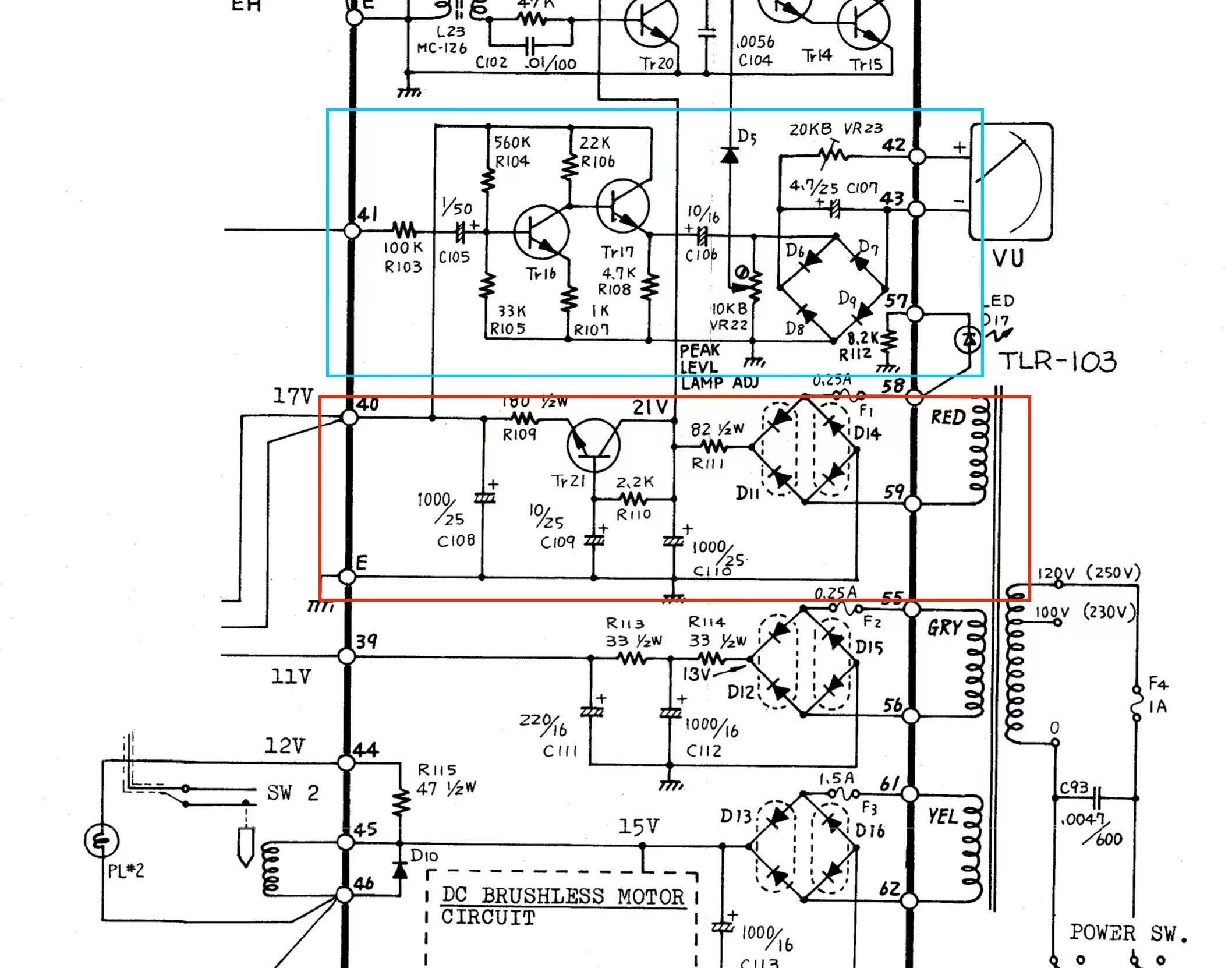
Problem description: The output voltage of pin 40 of my Roland RE-201 power board is about 12V, but according to the specification, it should be between 16-17V.
In addition, the device also has the following problems: the VU pointer keeps jumping, and crackling noise can be heard if the power amplifier is connected. I suspect that these problems are caused by insufficient output voltage.
Inspections and repairs carried out:
Preliminary check: I checked the red area on the power board, specifically the resistance of R109, and found that the resistance of R109 was 192 ohms, I have replaced this resistor. Situation after replacement: After replacing R109, the output voltage is still 12V, and there is no improvement. The VU pointer is still beating, and the crackling noise still exists. I also checked all the parts in the blue area and found no faulty components.
Can anyone give me some advice?
(Should I consider disconnecting the two leads of the pin 40 output to make sure the low output is not caused by the load?)
5b8bdc0d0bd1cd07.jpg
 
How about following the schematic and veryfying that you ARE indeed getting 21V or so before the regulator for that supply rail? That's kinda-sorta what that "21V" is there for...
 
How about following the schematic and veryfying that you ARE indeed getting 21V or so before the regulator for that supply rail? That's kinda-sorta what that "21V" is there for...
Thank you for your answer. I tried to use the black test lead of the multimeter to connect to ground. The red test lead was connected to C or E of Tr21. The value I got was 25V or 24V. In addition, it seems that it was because I made a mistake in measuring D11 and D14 with the black and red test leads, which caused the fuse. It burned out, but I replaced it with a new fuse. I'm not sure if it's the fault of D11 or D14. I don't know how to judge whether they are good or bad. What should I do next?(I also have a portable oscilloscope and if I need to use it to check a circuit, I follow the instructions.)
 
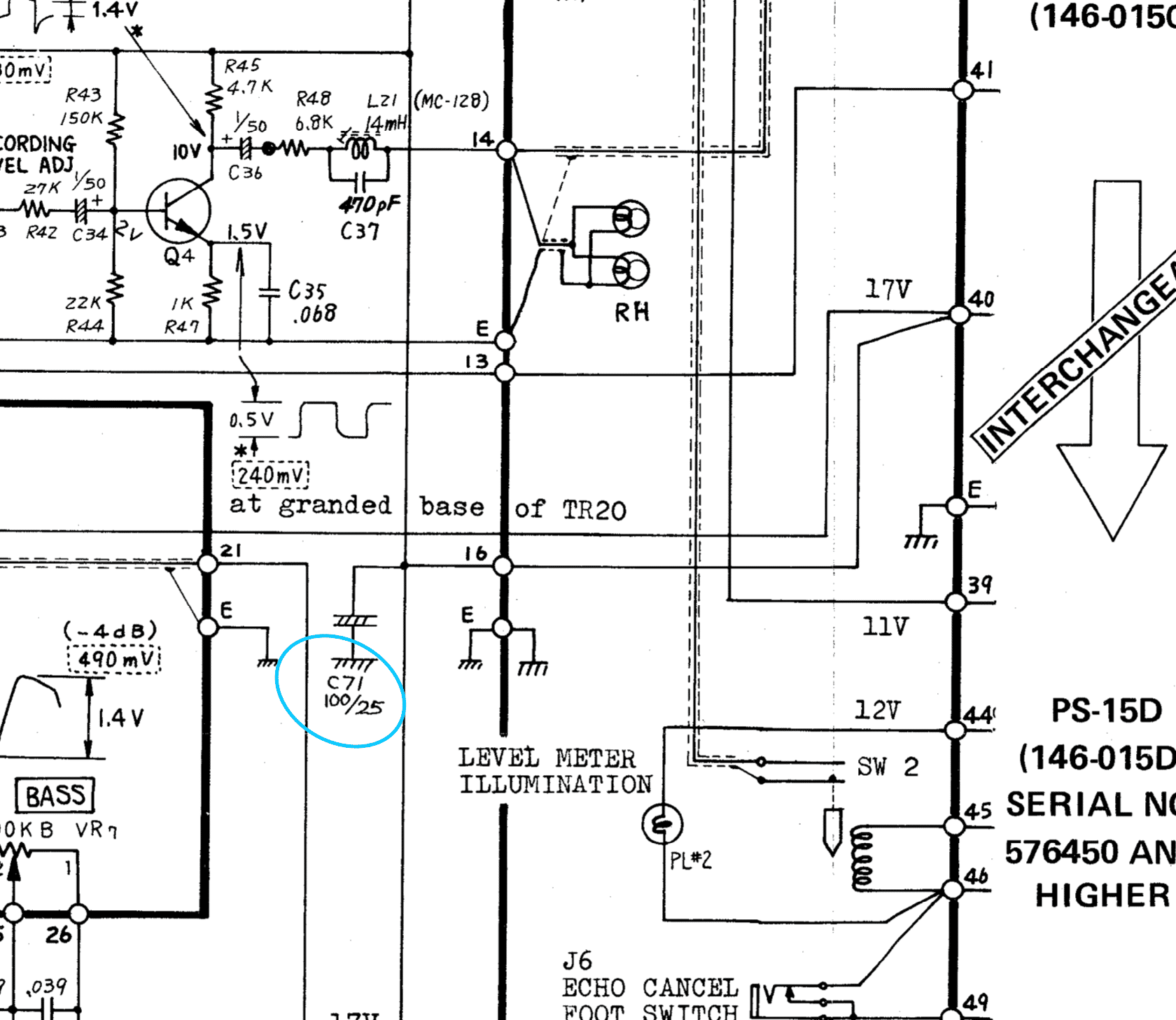
The latest update is that after I replaced C71 on the reverb echo board, I no longer hear the crackling noise. but The pin 40 still output 12.56V ,Soon after, the crackling sound came back again (I lost the echo delay)
43eb9c5c30b2d66a.png
 
Last edited:
Hello, everyone. I will announce the results of my measurement. I hope to know what should be done next.
C110 is measured with a multimeter to get 20.9V, and C108 is measured to get 14.9V.
 
Hope to get some help, will D10 on pin 44 and 46 affect the output voltage of pin 40? I found that the value of D10 is not normal. I am not sure if it is because pin 40 affects D10 or if D10 affects pin 40.
 
Hope to get some help, will D10 on pin 44 and 46 affect the output voltage of pin 40? I found that the value of D10 is not normal. I am not sure if it is because pin 40 affects D10 or if D10 affects pin 40.

You're telling us that as if we magically know where D10 is, what it's connected to, or what it does.

What does that 16-17V (that's supposed to be at pin 40) feed?
 
D10 is connected to pins 44, 45, and 46. 44 and 46 are the bulbs responsible for the VU meter. It did not work, and the measured voltage was too high. I am not a professional maintenance person, so I may not be able to convey it to you accurately. The 16-17V on pin 40 should be responsible for powering the jack board and echo board.
 
Oh, noticed D10 in the first snippet of schematic after all.

https://resources.altium.com/p/using-flyback-diodes-relays-prevents-electrical-noise-your-circuits

No idea how you measured it, but that's in parallel with the coil of relay SW2 (reed relay?).

If those VU meter bulbs are burnt, "of course" the voltage will be too high there, since there's nothing left to load down that voltage rail. Pretty sure that has nothing to do with the other / initial problem you described, though...
A good news and a bad news, I replaced some resistors, and now the output of pin 40 has reached 16.3V, which is the normal range. You can still hear a little noise when connected to the amplifier, but it has been greatly improved, but the process of replacing the resistors I accidentally broke the white pin of the selector , it should be in the third blue area, but I soldered it in the second red area, and then I found that there was no signal when I connected the guitar to play, and there was no signal from the instrument and microphone, including the PA, so I changed it Completed the third blue zone and still no signal, do you have any suggestions for this?
IMG_2683.jpg
 
C110 is measured with a multimeter to get 20.9V, and C108 is measured to get 14.9V.

And what of the emitter of Tr21? Is the voltage at C108 low because the voltage output of Tr21 is low, or because more current than expected is flowing through R109?

I found that the value of D10 is not normal.

What does that mean? The forward voltage of the diode is not what you expect? Or the voltage at pin 45 is not close to 15V?

I replaced some resistors, and now the output of pin 40 has reached 16.3V

Which resistors? Do you understand why those would cause the voltage to be low?

I accidentally broke the white pin of the selector

What are you calling the selector? Sw4 which changes the output level? Or the mode select switch which is labeled with Sw 1a through 1d, but does not show the connection details?
 
And what of the emitter of Tr21? Is the voltage at C108 low because the voltage output of Tr21 is low, or because more current than expected is flowing through R109?
I probably remember that when it was detected, Tr21 was about 15V. When it passed R109, the voltage became about 12-13V,I also borrowed my friend's re-201 for comparison. His tr21 launcher was about 19v, and after r109, he got 16-17V.
What does that mean? The forward voltage of the diode is not what you expect? Or the voltage at pin 45 is not close to 15V?
I first used a multimeter to measure pins 46 and 44, and I got about 20V. I think this is the reason why the light bulb can't light up or is damaged, so I replaced the D10, but the voltage is still about 20V.
Which resistors? Do you understand why those would cause the voltage to be low?
I replaced the R104, R105, R106, R107 and R108 in the blue area, because when I used a mobile oscilloscope to measure them, they were not stable DC signals (although their resistance values were completely correct, I still replaced them, and finally got a 16-17V signal at pin 40). I used a re-201 power supply board that my friend didn't need, and there were the parts I needed, thank goodness.
What are you calling the selector? Sw4 which changes the output level? Or the mode select switch which is labeled with Sw 1a through 1d, but does not show the connection details?
As shown in the picture above, it is a mode selector, but I suspect that the output no signal may not be directly related to the disconnection of this lead. It just happened to be disconnected during the 17V output of pin 40. I found that the output current of pin 40 will go through the mode selector, input and output (I will provide the circuit diagram below)
 

Latest posts

Back
Top