S800 Support Thread

GroupDIY Audio Forum

Help Support GroupDIY Audio Forum:

This site may earn a commission from merchant affiliate links, including eBay, Amazon, and others.
Ya, well I certainly would've used four 1U 2 channel ones if I had known how annoying this case would be.  But, alas.  Does anyone have a part number for an adequate large heat sink that will work with the PSU?

Thanks,
Sig
 
I missed the boat on puruscha's cases so I need to drill my own.  Do you have a layout, or any advice?

i actually just cut the aluminum face on a table saw with a metal blade and then just measured the center of my pots across.
basically...just grab a caliper a ruler and a pencil and you will figure it out.
Even after drilling holes, some of it had to be nibbled and enlarged to fit things right. The actually printed plate i put on top of the backing plate hid the problems nicely though.
Its still a touch of ghetto though, i dont think i could get any of my projects to look as nice as some of the prefab stuff offered on the black market.
I still have to take pics of mine...i dont have internet access at home and i only work a few days a week and i am busy with other stuff...so it is a pain sometimes to get to the web.
 
peterc said:
Neon

2 x 47k's in parallel will be fine.

Brolik

I did an 8 chan Green  with a single PSU & I used a lump of aluminium about 50 x 25 x 5mm & it got HOT! Worked fine for a good few months but I then mounted the regs on the chassis for longevity's sake.

Peter

I'm trying my best to picture what mounting the regulators to the chassis looks like, and how it would be achieved...what has everyone else been doing in their 8 chn units? 

Thanks,
Sig
 
When mounting the regs on the chassis, I meant onto the case. So it meant screwing the regs to the side of the box (with heatsink compound & insulating washers) after sanding the paint off beneath the regs. Then using flying leads to connect the legs of the reg to the PCB.

Peter
 
well, i have never had to mount the regs on any of my projects, but i would assume you could just drill a hole in the chassis, and mount the regulator itself right to the chassis(provided it is aluminum) and use a thermal pad or bit of paste...
then use some good thick wire soldered to the legs of the reg going into the board...a bit of heatshrink and i would think that would be fine.
Or go to a recycle center and see if you can find an old computer power supply and rip the big aluminum heatsink out of that cut those and use them as need be.
They are usually a few inches long and tall. Could probally get two regs right on the  board attached to one heatsink after you trimmed it to fit in a 1U.
If you are using the v6 green psu and have omitted the phantom power circuit, the regs should be in a position to allow the sharing of one large heatsink.
I dont know if you need a bigger heatsink than that...depends on the heat you are gettign and current you are pulling.

Here is an idea of the size of the heatsinks you can get out of a computer psu:
http://img192.imageshack.us/img192/8704/img09662at.jpg
sometimes you get smaller ones like this:
http://www.techwarelabs.com/guides/misc_mod/psu_mod/HeatsinkClearance.JPG
but i think they should be pretty decent. you could probally trim a bit one around the ps board if you have room..
like this:
heatsinkck7.jpg


might work, may not...like i said, depends on the heat you are really getting.

 
peterc said:
When mounting the regs on the chassis, I meant onto the case. So it meant screwing the regs to the side of the box (with heatsink compound & insulating washers) after sanding the paint off beneath the regs. Then using flying leads to connect the legs of the reg to the PCB.

Peter

Cool, ok I think I'll try this, as weird as it's going to "feel" doing it...wish these 8 chn cases weren't SOOOO damn tight.

How are you guys mounting those LED's to the front panel?  A dab of silicone?  Mine don't fit super snug, and I'm afraid some dumb shit is going to poke one of them in, and I'll have to take the whole damn thing apart to fit it in again.

Thanks,
Sig
 
Siegfried Meier said:
How are you guys mounting those LED's to the front panel?  A dab of silicone?  Mine don't fit super snug, and I'm afraid some dumb shit is going to poke one of them in, and I'll have to take the whole damn thing apart to fit it in again.

I took some sheathing from the leads of my power transformer to insulate the leads on the LEDs (before soldering anything to the LEDs).  When the LED is pushed through the hole behind the front plate there is enough friction to keep it from going anywhere.  Finally when my front plate was in place I pushed the LEDs in to the holes where I wanted them, put a small flat head screw driver between the leads to the LEDs and gave a gentle twist to expand the leads(between the front and backing plate).  This pretty much locked them in to place (thus far).

Maybe then add a dab of hot glue from behind?  I didn't, but mine seem solid.
 
Hi Geoff004 ,
A cool pic wd be usefull for bad english ...(Like I !)
Could you , please??
Thx!
Edit : I meant people who do not understand english very well...
 
Ya, I don't really understand what you mean.  My LED's extend out a few inches and are shrinkwrapped, but they don't sit tight in the front panel holes, so they slip out.  I tried hot glue, but by the time the front panel was nearly on, a few had broken loose.  Man, is this case a bitch.  Everything is so tight and bulging and squished, it's so difficult to get anything to work.  The PSU should definitely NOT have been inside this unit, and I wish I had thought of this before.

Gonna keep trying some things.  On a good note, all 8 of my channels are wired, tested and calibrated, and sound fantastic!

Thanks,
Sig

EDIT - it appears there are certain LED's that fit very tight and snug, and some that don't, even though they're all 3mm.  I happened to pull one out of the drawer for the power, and it fit perfect.  So, I guess I have to cut all these off and try to find some replacements that fit better.  :'(
 
Have you tried paste "nor spike/nail nor screw" ??? :p (sorry it's a translation of what we got here for paste type)

EDIT : http://www.toutcoller.com/pub/produit/produit-ni-clou-ni-vis,id-170.html
 
Siegfried Meier said:
Ya, I don't really understand what you mean.  My LED's extend out a few inches and are shrinkwrapped, but they don't sit tight in the front panel holes, so they slip out.  I tried hot glue, but by the time the front panel was nearly on, a few had broken loose.  Man, is this case a bitch.  Everything is so tight and bulging and squished, it's so difficult to get anything to work.  The PSU should definitely NOT have been inside this unit, and I wish I had thought of this before.

Gonna keep trying some things.  On a good note, all 8 of my channels are wired, tested and calibrated, and sound fantastic!

Thanks,
Sig

EDIT - it appears there are certain LED's that fit very tight and snug, and some that don't, even though they're all 3mm.  I happened to pull one out of the drawer for the power, and it fit perfect.  So, I guess I have to cut all these off and try to find some replacements that fit better.  :'(

I have some few tips and suggestions for making better use of the space in the rack to comfortably fit in the PSU's, but agreed, the case could have been deeper, those wires are REALLY squished in there. I will post some pics on Monday/Tuesday... the key is NOT use the suppled brackets....

RE the LED, I've been using super/crazy glue, just make sure that the LED's fir the rack, add a dab of super glue and it will hold VERY fast... no problems doing this on the 4 1U units I built, same plan for the 4U.

Cheers

Matt


RedNoise said:
A cool pic wd be usefull for bad english ...(Like I !)

Hopefully my pictures will help better explain.
This is what I did and I'm content to live with it.
Here's what the LED looks like before installation.  Just strip and cut sheath to length and push it on to the LED leads.  Try to use thicker sheathing (like from extra wire from a power transformer).  Then solder wires to the LED.  I end with a little electrical tape or heat shrink on the solder joints.  Don't forget that the LEDs need to be wired properly to work - they have + and - ends (speaking from experience, it's a pain if not done correctly the first time).
s8001.JPG


Once the LED is pushed in to place I gently open up the leads with a screw driver.  My LEDs haven't moved in a couple of weeks of use.
s8002.JPG


I'll be curious to see how you worked your rack matta.  I used only the rear brackets.  I also drilled out the hole on the boards so that the PCB would sit flat to the bottom of the case.  The first 4 boards sit fairly perpendicular to the front panel. The last 4 are at a decent angle.  But I managed to fit everything with XLRs and DB25 connectors, and the entire PSU.  AC noise is only visible (I honestly haven't listened for it, but it came in at about -75 db on the waves analyzer) on channel 8 when I boost low frequencies - not the bottom pot (60/120 boost) but the one above it with the sweep-able freq.  I think it's because the pot is about 1 cm. from the transformer.  Everything else is totally quiet.
 
matta said:
Siegfried Meier said:
Ya, I don't really understand what you mean.  My LED's extend out a few inches and are shrinkwrapped, but they don't sit tight in the front panel holes, so they slip out.  I tried hot glue, but by the time the front panel was nearly on, a few had broken loose.  Man, is this case a bitch.  Everything is so tight and bulging and squished, it's so difficult to get anything to work.  The PSU should definitely NOT have been inside this unit, and I wish I had thought of this before.

Gonna keep trying some things.  On a good note, all 8 of my channels are wired, tested and calibrated, and sound fantastic!

Thanks,
Sig

EDIT - it appears there are certain LED's that fit very tight and snug, and some that don't, even though they're all 3mm.  I happened to pull one out of the drawer for the power, and it fit perfect.  So, I guess I have to cut all these off and try to find some replacements that fit better.  :'(

I have some few tips and suggestions for making better use of the space in the rack to comfortably fit in the PSU's, but agreed, the case could have been deeper, those wires are REALLY squished in there. I will post some pics on Monday/Tuesday... the key is NOT use the suppled brackets....

RE the LED, I've been using super/crazy glue, just make sure that the LED's fir the rack, add a dab of super glue and it will hold VERY fast... no problems doing this on the 4 1U units I built, same plan for the 4U.

Cheers

Matt

Thanks for the tips.  Are you referring to the brackets that hold the modules in, or the brackets on the front panel that holds the space?  Because I'm not even sure how I'm going to get the front panel on and have everything line up.  It's very difficult to make all the pots come through the holes, very tight.

Thanks,
Sig


Ok,

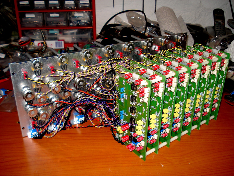
This may help. What I did was get 30mm standoff and join the boards together, I then added some 3mm weather stripping on the top and bottom of the case, when you screw it together it clamps down on the PCB's, holding them all in place.

8_channel_PCB_wired.jpg


Cheers

Matt
 
Great idea Matt.  This also opens up more space on the right side for the PSU.

What about those brackets for the front panel?  I still can't seem to fit them right without it slipping out.  Anyone else have issues getting  their front panel on nicely?

Thanks,
Sig
 
Siegfried Meier said:
Great idea Matt.  This also opens up more space on the right side for the PSU.

What about those brackets for the front panel?  I still can't seem to fit them right without it slipping out.  Anyone else have issues getting  their front panel on nicely?

Thanks,
Sig

Hey Sig, my panel was fitting really tricky and tight, so I opened up the pot holes with a drill (just taking the paint off), everything sat much better after this. I ended up gluing the front panel brackets in place.. cause they always slipped out!
 
Tested some different chips the other day. Some OPA604s and a set of OPA134. the 134´s won. OPA134s are quite expensive, but if you don´t like hiss, then I would recommend them over the TL071s.  Some might argue that I have lost some of the trident sound... but I don´t know. To my spectrum-analyzer, things looks almost the same when I compare them visually.  But the noisefloor dropped down from -94 to -105 !!  Now I can use this EQ on the master too! yeeeee!

PS ; you must be careful turning any of the boostknobs to over +10 (or something like that). If you look at a spectrum-analyser, and turn the high-band-boost all the way up, fuckt up things happen all over, including an ugly bassboost. (happened with all the chips I tested)


Latest posts

Back
Top