SB4001 Support / Build Thread

GroupDIY Audio Forum

Help Support GroupDIY Audio Forum:

This site may earn a commission from merchant affiliate links, including eBay, Amazon, and others.
It's all good, bro.  happens to the best of us!  er, happens to those of us who have assembled a kit for selling lol

but anything between 1K5 and 2K5, 1W will be fine, it's merely a current limiting resistor for the meter backlight.

Is there anything wrong with using the existing 1/4 W 1k5 that's left over?    Will it just make the meter backlight extra bright?  Cuz that might be kinda cool.    Or will the lower wattage resistor make the Meter backlight pop or perhaps the resistor itself will burn out?

This is an easy build!!!  I love it!!!

made it this far before stopping.  triple checking takes a LOOOONNNNGGG time, but it's worth it.  there are so many resistors in this.  *shudders*

If anyone could post a pic showing how to jumper L2R (it has 3 different pads), it'd be appreciated.  Only thing left is the trimmers, pots, switches, and then assemble/calibrate this little guy!

imag0164ff.jpg
 
Hey, no worries on sending me the resistor.  Save yourself the time and the postage, I've got something suitable here.

Chuck, you'll burn out the 1/4W if you use it so don't bother trying.
 
horvitz said:
Hey, no worries on sending me the resistor.  Save yourself the time and the postage, I've got something suitable here.

Chuck, you'll burn out the 1/4W if you use it so don't bother trying.

Correct, it's pulling approx 5/8 of a watt.
 
they sit next to the 4 ICs.

I also had 2 of those left over.  I think they were extras in my kit, tho.

Can anyone post a pic of how L2L/R should be jumped?  There are 3 pads to pick from. 
 
Yea, I already stuffed the 51R's, there are 2 extra.
Looks like the 2 outer holes where it's marked "JUMP"
(Jumper L1L/R & L2L/R Note*** - the 3rd pad in the middle of L2L & L2R is a ground connection, and has nothing to do wth L2L or L2R, ignore this 3rd pad.)

 
Grayhill switches:

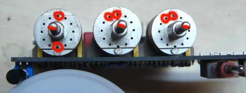
You will need to insert the stopping pins into all 4 grayhill switches.  They are very tiny and easy to lose so make sure to do this in an open area where they can't accidentally fall into the abyss.
Before inserting the pins the shaft should beroytated so that the flat of the shaft is towards the left.  It should already be towards the left by degalt, so there should be nothing that you'll need to do in this regards, however be sure to verify it is pointing towards the left before you insert the pins.

There are three 2X6 switches and one 1X12 switch:

The 2X6 switches, pins should be inserted at 12 o'clock and 6 o'clock.

The 1X12 switch: single pin should be inserted at 12 o'clock


I don't understand this. Left in relation to what? By default the flat part is facing the pins. Is 12 o'clock the top of the and 6 o'clock by the pins?
 
I think he means you shouldn't have to change anything from how they arrive from the factory. 

an example: 

V2_GRAYHILL_STOPERS.jpg


The switch on the left in the above picture is showing the pins at 12 and 6.  note the angle of the shaft (that's what she said)


In the rack itself, do we need to jumper the stereo link pins? 
 
Everything is stuffed except the TRS and the missing 1 watt resistor. I'm waiting for that final piece before finishing. I've gotta say that I'm worried about this thing firing up right away because I spent so much time working on it.

How critical is the value of the 1 watt 1k5 resistor? I'm sure I can find some equal valued half watters to parallel that would get me in the area of the 1k5, but not exact.
 
therecordingart said:
Everything is stuffed except the TRS and the missing 1 watt resistor. I'm waiting for that final piece before finishing. I've gotta say that I'm worried about this thing firing up right away because I spent so much time working on it.

How critical is the value of the 1 watt 1k5 resistor? I'm sure I can find some equal valued half watters to parallel that would get me in the area of the 1k5, but not exact.

Mentioned it a little while back but it probably got burried.  This 1W 1K5 resistor is a current limiting resistor for the Meter backlight.  Its value is not critical at all, though you don't want to go any lower than 1K5.  Wattage is critical though as it's dropping alot of volts, burning approx 5/8W.  Reasonable value is anything between 1K5 and 2K5.  If you have two 1/2W 1K resistors or something close, that would work just fine.
 
It's alive! Meter lights up and reacts to an input signal. I haven't tried listening to the signal yet. Gonna wait for the calibration info before I bother.

Thank you so much for this...what a deal. Only took 17 hours! haha
 
ruckus328 said:
therecordingart said:
Everything is stuffed except the TRS and the missing 1 watt resistor. I'm waiting for that final piece before finishing. I've gotta say that I'm worried about this thing firing up right away because I spent so much time working on it.

How critical is the value of the 1 watt 1k5 resistor? I'm sure I can find some equal valued half watters to parallel that would get me in the area of the 1k5, but not exact.

Mentioned it a little while back but it probably got burried.  This 1W 1K5 resistor is a current limiting resistor for the Meter backlight.  Its value is not critical at all, though you don't want to go any lower than 1K5.  Wattage is critical though as it's dropping alot of volts, burning approx 5/8W.  Reasonable value is anything between 1K5 and 2K5.  If you have two 1/2W 1K resistors or something close, that would work just fine.

Great that's what I did, I went with 3.3k though, shouldn't do any harm right?
 

Latest posts

Back
Top