SB4001 Support / Build Thread

GroupDIY Audio Forum

Help Support GroupDIY Audio Forum:

This site may earn a commission from merchant affiliate links, including eBay, Amazon, and others.
mulletchuck said:
Hey, ruckus.  This thing sounds AWESOME as a single channel compressor too!!!    had some fun with it tonight:  http://twitpic.com/7p41rj <-- video with clean audio

nice playing!
 
emrr said:
he sent it twice, to your payment email address.
Thanks for the reply, but I did not receive them like other mail outs he did. He had accidently forgotten to add me to the email out list so I am just trying to get hold of them now, since I can not move on this build without them.
 
dandeurloo said:
mulletchuck said:
Hey, ruckus.  This thing sounds AWESOME as a single channel compressor too!!!    had some fun with it tonight:  http://twitpic.com/7p41rj <-- video with clean audio

nice playing!

I put up a full video in the Brewery where I use the SB4001 as a tracking compressor.  http://www.groupdiy.com/index.php?topic=46860.0
 
DONE!

there are 4 small nuts left and i have no idea where i forgot to use them  ;D
the small tool for the knob-screw was not included, right?
i'm also a bit confused about the right orientation of the tl704? should i align the "cutout" of the chip-body with the one in the socket? edit: answer found here

afterwards i only need to build a 51x-rack to use this baby  ;D
 
ruckus328 said:
STEP20.JPG

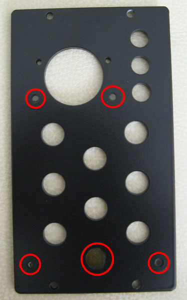
Can you please verify which holes you are scraping the paint off in the back of the front plate, refer to pic below. Is there any other areas to be scraped or mods to be done elsewhere?
checkPaintScrape.jpg


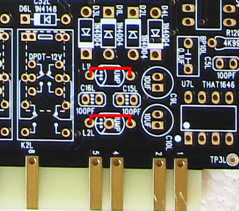
In regards to jumping the L1L, L2L, L1R, L2R, to those unsure, I think he means this. Showing only the Left board, but the same should be done for the Right board. Please confirm.
jumpL2L.jpg
 
That's the correct method for jumping them, yes.  Also, those are the proper places to remove paint.  Finally, there is one more jumper near the meter-side of the board.


http://www.zshare.net/download/9751894262ef9414/
Ratio 2


Attack .20


Release .7


Blend WET


SLOPE


Thresh: 3rd dot


Gain: 8db

and the original ITB version:
http://www.zshare.net/download/97512095832a2f40/
contains 2 files, just ignore the SB4001 from that cuz i didn't write down the settings. 
 
Ruckus, regarding the error on your PCB board and the fix for it that you have emailed to everyone. Is there another solution than bending that 1meg ohm pots pins and soldering to the other pin?

Like cutting a trace or making a jump wire somewhere? Just incase the pins are accidently snapped off or people are struggling to get the solder small enough to do your fix and avoid shorting anything and possibly damaging the unit?

Is there a pot available that you can just buy to replace the current 1 meg ohm pot in your kit than doing your mod fix?

So is this just an issue that causes the release times not to match the screen print on the front panel only or is there more to it?
Maybe people might be better off just relabelling their front panel?
 
i will wait some time until more people finish this with better test equipment as i'm not interested in taking it apart more than once...

this fix is only for the variable release, right?
 
SKJGProject said:
i will wait some time until more people finish this with better test equipment as i'm not interested in taking it apart more than once...

this fix is only for the variable release, right?
Are you noticing anything funny going on with your build?

Does the release time work normal except it works backwards? Like when you adjust the knob for a longer release, does it become a shorter release or does it act in any other way?

 
well screw me for building this without even owning any kind of lunchbox, but i have so much stuff sitting on my bench
where some parts are missing so i decided to finish the "all-included" kits first

NOT calibrated or tested at all so far
 
SKJGProject said:
is it necessary to jump jmp3l&r? ruckus only mentioned 1&2...
I was also confused as well, since he placed a note saying must jump on the other set item list but not on 3L and 3R list.

But if you look at one of his pics below at the bottom left, it has an item jumped from the list 3L/3R list, so I am presuming it must be jumped.

STEP6.JPG
 
emrr said:
if you wire the sweeper leg of a pot to an outer leg, it becomes a rheostat.  Look it up. 

So this means the rheostat connection isn't present on the circuit board, and I assume ruckus finds the bent leg to be the best solution.  Since he modified all of his production units I would also assume the pots can take it just fine.

So is the release pot not working at all or did he wire the wiper to the wrong pin? My unit is at the studio so I can't confirm...funny we didn't notice an issue, but I'm not so sure the variance has been used at all.

If the wiiper isn't wired to anything on the PCB won't a jumper suffice without pulling the pot out?
 
First I would to say thanks for a great kit.  I finished building this kit over a week ago and have been using it in the studio for the last week.  No issues on first fire up and calibration went smooth.  It sounds great!!

I'll have to do the mod later this week....

SKJGProject said:
is it necessary to jump jmp3l&r? ruckus only mentioned 1&2...

I jumped 3L/3R when I built mine as I had saw it jumped in the picture also.
 
therecordingart said:
So is the release pot not working at all or did he wire the wiper to the wrong pin? My unit is at the studio so I can't confirm...funny we didn't notice an issue, but I'm not so sure the variance has been used at all.

If the wiiper isn't wired to anything on the PCB won't a jumper suffice without pulling the pot out?

The wiper is connected to the wrong pin, so working in reverse.  The only logical way to correct this is the instructions I gave, there's no way to correct it whatsoever without removing the pot, even if you wanted to cut & jumper - the traces run under the pot so you'd have to remove it even then, and you'd need to perform 3 cuts and 2 jumpers, much more simpler way is to bend the lead over as I instructed, leads will be fine, they're very maleable, even if you were to break it (highly doubtful), then you could just use a piece of jumper wire on the pot to create the short.
 
Ruckus, can you please post pics of front, sides, bottom, top and back of the modded pot soldered in place on the unit.

I would like to see how it looks in place so that I can decide whether to do your mod or fashion my own, with the pin bent back and use a cable to short the other pin. Need to know what the spacings are.

Concerned at how the bent pin underneath may short the pad and may be prone to shorting when the unit is bumped, jiggled, etc.

Also if you were to cut the traces and jump instead of your bent pin mod, how would you do it?
 
Canidoit - you're making this 100 times more difficult than it is.  Simple instructions were given on how to fix it, you can do it, or not do it, it's up to you.  But you're reaching at straws here and making issues when there are none.  This is a very simple fix.

OK, moving on............
 
SKJGProject said:
DONE!

there are 4 small nuts left and i have no idea where i forgot to use them  ;D
the small tool for the knob-screw was not included, right?
i'm also a bit confused about the right orientation of the tl704? should i align the "cutout" of the chip-body with the one in the socket? edit: answer found here

afterwards i only need to build a 51x-rack to use this baby  ;D

There are only 4 nuts - they hold the faceplate to the U-Bracket.  There are also four 1/8" long standoffs (they look like nuts) - those are used to space the faceplate from the u-bracket (see pics in beginning of the thread)

Tools aren't included, it's a 1/16" allen/hex wrench you'll need.  A 1.5mm will work also for you metric guys.
 
Back
Top