schemo question bout this pultec and adding frequencies

GroupDIY Audio Forum

Help Support GroupDIY Audio Forum:

This site may earn a commission from merchant affiliate links, including eBay, Amazon, and others.

pucho812

Well-known member
Joined
Oct 4, 2004
Messages
15,009
Location
third stone from the sun
Was studing this schemo over lunch. I read through the meta's and ran into CJ's topic of adding extra frequencies to a pultec.
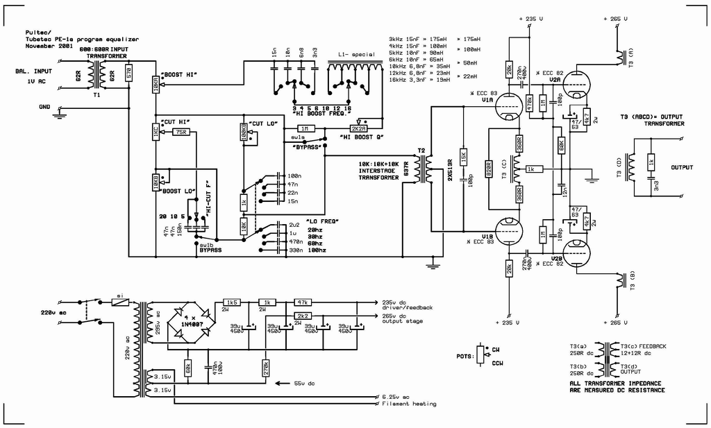
pultech.gif


I can't locate which Inductor if any value ties to the bass boost or cut as well as which one ties to the high cut. I'm just not seeing it... :?
I see where the treble frequency select connects into L1 so what am I missing :?
 
[quote author="RogerFoote"]The inductor is only in the hi boost section...
The lo boost, lo cut and hi cut are all RC filters.[/quote]
Please don't say this too often - or use a smaller font size.
I mean, I found it quite sobering when I found out only a small part of the Pultec-filtering has the magic mystery coily thingy stuff TM going :evil: :wink:
 
Yes :grin:
Maybe it means the magic of Pultec is a combination of irons, capacitors, tubes, frequency choices and an excellent design of course.
 
[quote author="laitue5"]Yes :grin:
Maybe it means the magic of Pultec is a combination of irons, capacitors, tubes, frequency choices and an excellent design of course.[/quote]
... and Dakaware, blue-ish paint and intimidating dimensions :cool:
 
[quote author="CJ"]Itr's the phase shift that the engineers like.[/quote]
I recall that being mentioned previously around here, most likely the AES-report.
About time we stop labeling about the amplitude stuff one would say.
Let's start Dymo-taping degrees phase shift :thumb:
 
Pucho, I had the same discovery - looking over the same schemo.

Sowter sells two different inductors for pultec - I wondered where the 2nd one (Sowter 9858) goes.
Finally found it in the midrange (separate) circuit: MEQ5.
 
o.k. I am having trouble on this. I got the high frequency's bost math to come out perfect but I am having trouble with the RC circuits. I can't get my math to come even close to those numbers there. Can someone do an example for me so I can reverse the example and understand. So far I know it's based off impedence so should I be using a ballpark figure like 2200ohms? or what :?
 
I would love an expanation of the impedance as well in the RC circuits! I understand the theory of the boost and cut filters from reading, but having little design or bench experience often have a gap in the understanding of their function in a circuit. Is it just a function of the resistor in series with the caps, and if so how do the pots preceding not contribute to the series resistance, and only to the ammount sent to the filter?
Sorry for the blockheaded questions, hopefully these will be fewer as my brain wraps around these concepts.
Ian
 
(from Gyraf pultec)
--so then the high cut would come through the 1k pot into the 75r and go to ground through whichever cap is switched in, if the bypass switch isn't engaged. I understand that there is frequency dependant impedance through the caps, but is the amount of signal sent through the 75r-cap network to ground also determined by the relationship of the boost and cut variable resistors?
--the low cut goes through the 100k variable, which sends a portion of the signal to ground and a portion to the output stage. Again, how do the 1k and 10k interact with this signal? Also, is the signal only routed through the first set of caps (on Gyraf: 100n through 10n) or does it also pass through the 10k and on to the second section of caps? I'm just wondering how the lower frequencies get to ground?
I tour quite a bit and can promise some free beers to those who i cross paths with for putting up with all of these boneheaded questions<G>
Ian
 
cool roger. so say I am looking at the bass boost. My total resistance is what 21Kohms?
I think I got it... now


Capacitive reactance is determined by the formula:

1 / (2 * pi * f * C)

where: 2 * pi = 6.2832; f = frequency in hertz and C = capacitance in Farads

am I on the right track :?
 
EDIT.

R=Xc

R= 1/2pi *F*C

C = 1/2pi * F* R

I got it now... :twisted: I now can plug my math in a get it all working... I knew I should have looked in the handbook for sound engineers first. totally worth picking up. :thumb:

Thanks for the help in the right direction roger. :guinness: :guinness: :guinness:
 
I think i have a handle, after a number of hours trying to make this much more difficult than it has to be<G>
Please, oh benevolent knowers of all these things, tell me if i am on the right track, that I may again record without my head bowed in shame.

On the RC sections of the circuit, the resistance is simply the capacitive reactance of each cap. So if you wanted to sub in some other frequencies, you would need to first know the caps and their associated frequencies so you could get the reactance, and then sub that into the equation with the "new" desired frequency. For instance, i calculated Xc= 3619 for the 2U2 at 20hz and Xc=5307 for the 1u at 30hz. If i was looking to put in a cap to boost 25hz, i would start by taking a Xc between those two frequencies, say Xc=4400 @25hz, then doing the math, i come up with around 1.45u. Which gets me in the ballpark/
trying not to let the card house get too high
Ian
 
yes, you got it.
let me see if i can dredge something up.

here is what I got for the eqp booster section.
note that the values are nowhere perfect.
nameplate values, in order to match real values, would require weird cap values.
Pultec did not want to buy a 0.047827 uf cap.
So if you want exact resonant freqs, you will have to trim things up.
Also notice that the reactance values from band to band are different.
You can't hear it, but it will show up on a simulator.

filter_values_post.jpg
 
Is there a standard you can sub in to calculate capacitor reactance values? I've been crudely playing with a crude model in LTSpice to see if I can add some more bands to the RC based bands, and it seems so tricky to track the pattern down that I might just buy some caps randomly and see what happens. I have a ton of extra switch options on the platform for this i'm using (up to 20), that it would be nice to fill those out. Did anyone come up with some decent values to add to those slots?

It would be nice to be able to take the high pass waaaay low for eqing basses, and also would it still function correctly with the frequency selector for low cut/low boost decoupled onto 2 switches?
 
The LC based high boost in the Pultec is relatively straightforward to understand and tweak.

The RC based sections are much harder. The reason for this is that there are two turnover frequencies for each. One where the boost cut begins and another where is flattens out again. The problem arises because it is not always immediately obvious from the schematic which pair of resistor values are relevant for any given band and the really obtuse way the original Pultec EQ is drawn does nothing at all to help you.

All is not lost. It is easy to identify the capacitors involved in each band.

The lo cut ones are near the low cut control in the schematic in post #1.

The low boost caps are the ones directly below the lo cut ones and are labelled lo freq.

The hi cut ones are by the switch labelled hi cut F

In all cases, the frequency is inversely proportional to the capacitor value. So, it you double the capacitance you halve the frequency and vice versa.

Cheers

Ian
 
Cool! Yeah the relationship seemed simple enough to roughly map out. so that 2 pole switch though, is that maintaining the “width” of that band via its cutoff points on either side? Or rather it’s drop and then plateau?

So say if it was decouple you could end up making wider or thinner bands? Or would the whole thing just go wiggly?
 
Cool! Yeah the relationship seemed simple enough to roughly map out. so that 2 pole switch though, is that maintaining the “width” of that band via its cutoff points on either side? Or rather it’s drop and then plateau?

The frequency where and RC EQ starts is generally fixed. From this point on the EQ rises or falls at 6dB per octave until the second turnover frequency kicks in when the EQ will plateau. The tone control varies the the second frequency and hence the amount of boost and cut. So basically the width as you put it just defines how much boost or cut you get.

Cheers

Ian
 

Latest posts

Back
Top