Silly Soldering Question...

GroupDIY Audio Forum

Help Support GroupDIY Audio Forum:

This site may earn a commission from merchant affiliate links, including eBay, Amazon, and others.

Commander Fluffypants

Well-known member
Joined
Jun 29, 2013
Messages
103
Location
Boston
I'm having trouble getting solder to stick to two wires that I'm attempting to solder to a board (the meter board of my 1176; the wires in positions 3 and 4 that go to 28 and 29 on the main pcb.) I already had wires in there, but they were a bit short, so I removed them and twisted up a new longer pair. To further complicate my situation, one of them is solid core. I was having a hard time getting the solder to work on the solid core wire. The solder always stayed with the iron. Then I noticed I was having the same issue with the stranded wire. While I'm new to DIY, I've managed to build a few things by now and have never had this problem, at least not to this extent. My only guess is that something about desoldering the old wires is what's making it difficult now. Perhaps I need to use some flux other than what's in my solder? Are the pads on the meter board in need of some treatment  or cleaning?

Thanks as always
 
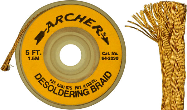
Desoldering braid and more flux are your friends here. When the tin doesn't get where you want, as long it's cooper, you need more flux, if you have trouble with old tin then you need the braid like this:
Desoldering-braid.jpg


I never seen one of those working badly, but sure there are, they are cheap so you test some and will find quickly if they work or not, some people have they favorites ones, I don't, this is the first pic on google for them, not a reference. Use a bit and cut it, don't keep using the same point till you get tired of it. Add a little bit of solder into the iron before, so heat gets faster and works much better, looks like counter intuitive to add solder when you try to desolder something but trust me, it's how it works.

JS
 
Might be an equally silly answer, but just to rule it out.

Are you tinning the wires before trying to solder them?

http://store.curiousinventor.com/media/images/how_to_solder/manual_tinning.jpg?1248414217

Gustav
 
Commander Fluffypants said:
. While I'm new to DIY, I've managed to build a few things by now and have never had this problem, at least not to this extent. My only guess is that something about desoldering the old wires is what's making it difficult now. Perhaps I need to use some flux other than what's in my solder? Are the pads on the meter board in need of some treatment  or cleaning?

What kind of solder are you using, and what kind of soldering tool are you using?
 
Once again, I'm blown away by the generosity of people on this forum, even for such a basic question.

I'm not at the studio right now, so I'm not exactly sure what solder I'm using, but I think it's somewhere near a 60/40 mix leaded with the flux in it. I've used this solder to make many cables and to make two CAPI VP28's and four 2520's and four 1731's, as well as all of the wiring in my 1176. My iron is an inexpensive Weller. I have a solder sucker and I was successful with it to the point that I could easily get the new wires in place. I would normally tin the stranded wire, but in this case, the hole is so small, it's easier to push the wire through and then tin it while it's poking through. As I said, I already had two wires in these holes. I did have a bit of trouble with the solid core wire the first time around, but not the stranded. I'm touching the tip of the iron to the pad and the wire, applying solder to the opposite side of where the iron makes contact. I even tried just touching the iron to the tip of the wire, while applying the solder to where the wire meets the pad and the solder still wicks up to the iron and comes off with the iron, leaving the wire and the pad with no solder at all. Sometimes if I jerk around, I can get the solder to blob onto the wire, but it doesn't make the connection between the wire and the pad. I tried heating the iron more. I tried heating it less. My problem is just these two wires with these two pads. It makes sense to me that the problem might therefore be related to  having desoldered the other wires, somehow changing something with the pads that makes it hard for the solder to stick... but what changed and how do I correct it? Internet research suggests additional flux, above and beyond what's in the solder might help and I'm going to try that next, but I was hoping someone here would recognize these symptoms and know exactly what's going on.
 
Are you using new, or salvaged/old wire?

I used to have a whole bunch of solid core wire that was scrounged from something or another. It was free, but I always had to use some sand paper on the conductor before it would accept solder. Same deal with stranded stuff; when fixing older gear, if I have to re-strip wires I'll also need to rough up the conductors a bit to get the oxidation/whatever off so that the solder flows easily.

Don't know if that's what you've got going on, but it reminds me of when that used to happen to me.

Do the pads accept solder when there are no wires through them?
 
Good idea on checking to see if the pads will accept solder with no wires in them. The wires are all brand new. I could only get so many colors at the first place I bought wires, so I went somewhere else and bought more and that's how I ended up with some stranded and others solid, but they're all new.
 
Plenty of good answers, but I would add that I Always tin before soldering wires, even in situations that are very tight... If you carefully twist the multi strand tightly and then use a very small amount if solder, making sure your iron is at the right temp for the solder, you should be able to have it tinned and not increase the diameter of the wire by a noticeable amount.... A pair if needle nose pliers should be able to compress it slightly if needed.  Best of luck!
 
It's often the case that solid core wire has an enamel / resin coating - in which case you'll never get solder to stick to it without using fine paper to remove the enamel. There is also multi-strand enameled copper wire; this is typically used by headphone manufacturers (methinks to prevent users from repairing the wire when it inevitably goes open circuit due to wear). However, I haven't seen this stuff outside of headphones.
 
thermionic said:
It's often the case that solid core wire has an enamel / resin coating - in which case you'll never get solder to stick to it without using fine paper to remove the enamel. There is also multi-strand enameled copper wire; this is typically used by headphone manufacturers (methinks to prevent users from repairing the wire when it inevitably goes open circuit due to wear). However, I haven't seen this stuff outside of headphones.

It was used in radio, to avoid skin effect on high frequency stuff, some radio frequency coils for example. I've heard some audiophoolery stating using this kind of wire will reduce the phase shift in a wire due to it's constant resistance in the conductor against the capacitance between conductors, I think someone did the math then and found would be something like 0.00001º in extreme cases, I could be off by a couple of orders of magnitude  :eek:

JS
 
OK, I tried flux and then I tried to see if solder would stick to the pads. It will not. I'm including the best photo I can manage with my iphone. It looks like the traces next to the pads are becoming exposed, but the pads don't seem to be lifted.  How do I proceed? New meter board? Or is there a way to convince this sucker to work? And if a new meter board, should I start fresh with all new switches, etc?

Thanks again.
 

Attachments

  • image.jpg
    image.jpg
    703.3 KB
For what I can see at the photo pads seems to be missing, if you think they are there try to measure continuity inside them or even better to another place where the track goes, press kind of hard at the points with sharp proves so measurement is ok, and if there is some oxide you break it's insulation and have it right. If there is no continuity you need to get some of the solder mask out leaving the tracks behind shown so you can solder directly into them or wire to another point with some insulated wire to avoid messing other things up and soldering there, a resistor leg at the top of the board may be the easiest point to do this, but could be done on any pad at the back of the board.

JS
 
My solution:

It works. Just saw that this was one of your suggestions, joaquins. I looked at the traces and they went to the easiest two places possible. Fixed in seconds. Those wires being the ones for when the meter is set to "GR," it's easy to know that they're working because the meter zeroes out when I set it to "GR. "

Once again, thank you.

Now I need to test the unit again to see if replacing those wires even solved my original problem.
 

Attachments

  • image.jpg
    image.jpg
    1.2 MB
Nice, great it worked out so quickly! Comment if it did solved the original problem.

For the next time add some tube shrink or some insulation so you don't have those long wires hanging around...

JS
 
I was noticing that AFTER I soldered the wires. Is it worth doing it again and clipping those wires closer or adding tubing?

I'm not sure it helped my problem and I'm noticing a new problem, but I'm going to take that to the Rev D thread.

Thanks again!
 
Commander Fluffypants said:
I was noticing that AFTER I soldered the wires. Is it worth doing it again and clipping those wires closer or adding tubing?

I'm not sure it helped my problem and I'm noticing a new problem, but I'm going to take that to the Rev D thread.

Thanks again!

It only worth if you notice any chances of getting a short from them, I doubt it because they should be pretty stiff with the solder and nothing un insulated is close to them, and as those kind of solder are pretty easy to stress better touch them as little  as possible. Too bad you still have problems...

JS
 
Back
Top