Simplest discrete op-amps

GroupDIY Audio Forum

Help Support GroupDIY Audio Forum:

This site may earn a commission from merchant affiliate links, including eBay, Amazon, and others.
"is this the kind of stuff you had in mind with this thread Dave?"

Well... no, not exactly. I was thinking of op-amps.

The notion of amplifiers optimized for different tasks has a lot of merit. But for the purpose of this thread, I was really thinking of an op-amp circuit for general-purpose use in audio, with useful closed-loop gain of at least 40dB or so. If we're willing to use different amp types for, say, preamps, mixing amplifiers, line amplifiers, equalizers, buffers, etc. then we needn't mess with the op-amp topology at all. Simpler two- and three-transistor circuits could fulfill these functions. But sometimes you need an inverting amp, sometimes you need a noninverting amp, sometimes you really need a diff input with equal input impedances. If you're only using one amp "module" for the whole project, an op-amp topology allows you the freedom of choice.

"I think the biggest reason why there was a divergence between the use of integrated opamps and discrete opamps in audio back in the 70's was the problem of driving a line at +0db. The then available integrated amps (lm741, 4558, 5534, etc.) just couldn't do it "

You don't specify what reference you're using for "0dB", but a 5534 can do +20dBM into 600 ohms. You can use a 5532 with both amps in parallel with small series resistors on the individual outputs (or in a push-pull arrangement) for even greater output. I definitely wouldn't mention the 5534/32 in the same breath as the 741 and 4558!

Probably the biggest problem with the 741 was that it was so slow it couldn't reproduce the top of the audio band accurately.
 
[quote author="NewYorkDave"]


The notion of amplifiers optimized for different tasks has a lot of merit. But for the purpose of this thread, I was really thinking of an op-amp circuit for general-purpose use in audio, with useful closed-loop gain of at least 40dB or so. If we're willing to use different amp types for, say, preamps, mixing amplifiers, line amplifiers, equalizers, buffers, etc. then we needn't mess with the op-amp topology at all. Simpler two- and three-transistor circuits could fulfill these functions. But sometimes you need an inverting amp, sometimes you need a noninverting amp, sometimes you really need a diff input with equal input impedances. If you're only using one amp "module" for the whole project, an op-amp topology allows you the freedom of choice.[/quote]

For a rather good GP discrete opamp this one was published by Deane Jensen (RIP) quite a few years ago. He is the same guy who is known for those very well engineered audio transformers.

http://members.psyber.com/dibsed//CIRCATS/je-990.pdf

He was pretty early to adopt computer based modeling for circuit analysis so I suspect the values are well dialed in. You might be tempted to drop in a different transistor pair since back in the day the LM394 was pretty much the only game in town for low noise and decent matching.

If you want to go crazy I think Toshiba may make some nice low noise Jfet pairs and the THAT matched bipolar pairs might just about drop in.

JR
 
The Toshiba good dual FETs (2SK389, 2SJ109) have been discontinued but are still widely available. The only ones they make now are surface mount and have sources tied together. Very sad.

However, Linear Integrated Systems has a substitute for the Toshiba N-channel dual which I haven't tried yet but looks good on paper.
 
The meaning is pretty well-known, but since you asked:

Yes, but what does it mean to you?

Just because there is a input diff pair and compl. followers on the output doesnt make it an opamp.

Im trying to help you.

From wikipedia:

For any input voltages the ideal op-amp has infinite open-loop gain, infinite bandwidth, infinite input impedances resulting in zero input currents, infinite slew rate, zero output impedance and zero noise.

All of the above is of course impossible in real life, but modern ICs comes close.

Seeing as youre not building the "perfect amplifier" i guess you can start with this;

http://www.groupdiy.com/index.php?topic=16313&highlight=urei+opamp

Its a poor opamp, but thats what you wanted, right? :razz:

You could bootstrapp the collector load in the voltage amplifier, but its cheaper to make a BJT CCS, and seeing as you already got the bias for that you might as well CCS the tail in the diff pair and while were at it...........well, you see where this is going.....
 
As usual Fred seems to have all the answers to this, and has the three types of op-amps categorised earlier in this thread:

http://www.forsselltech.com/JFET-993%20Test%20c.pdf

http://www.forsselltech.com/DLR1_3.PDF

and his “Unity Gain Buffer Module”

What I would love to get from this discussion are the design decisions and tradeoffs that the designer has to consider for the three types and what specific advantages certain topologies provide in comparison to others. E.g. For the Unity gain stable version, can we simply remove the 2nd (voltage gain) stage from a typical 3-stage op-amp?

Does anybody have any good examples of the three types of op-amp we can look at and discuss?
 
JFETs (2SK170, 2SK389, 2N4393, etc) are not good drop-in substitutes for the LM394. I have tried. The vast speed created in the LTP makes the original 990 circuit unstable even at higher gains, the Bode plot changes. You need to redo the VAS to make it right. The LM394 is around, see Digikey, but its price is climbing slowly to MAT02 levels. In five years these parts might disappear altogether.
 
[quote author="tk@halmi"]JFETs (2SK170, 2SK389, 2N4393, etc) are not good drop-in substitutes for the LM394. I have tried. The vast speed created in the LTP makes the original 990 circuit unstable even at higher gains, the Bode plot changes. You need to redo the VAS to make it right. The LM394 is around, see Digikey, but its price is climbing slowly to MAT02 levels. In five years these parts might disappear altogether.[/quote]

Agreed, I hope it didn't sound like I was suggesting one could just drop in fets. However the higher Vth and low transconductance could give you a nice GP audio opamp once you properly dial it in, maybe even buy a little more GBW/slew rate, not that the basic design was deficient.

I have found that I could cover a lot of bases with GP bi-fets for high impedance apps and a 5534 or newer equivalent for low impedance apps. A fet input with low enough ein could come closer to a universal GP audio opamp. DC offset might be slightly compromised vs. precision dual bipolar.

The 2sk170 was probably the part I was thinking of. I believe I used the single version of that (2sk117?) in my last phono pre and that was a very nice part. That was also 20+ years ago.... The really low noise bipolars I liked for mic preamps are now obsolete so I'm not surprised if other special interest parts fade away too as modern engineers are more inclined to use off the shelf IC solutions.

JR
 
[quote author="JohnRoberts"]In a basic fet follower using a resistor from source to ground to set the device operating current the Vg-s will change with signal swing causing distortion as this change in Vg-s subtracts from the signal at the source follower output. If you instead load the source with a current source the Vg-s is more constant so you eliminate that particular distortion source.[/quote]

Thanks for the explanation JR and Wavebourn, appreciate your patience with a beginner... My reason for asking is that I had a feeling that in this follower configuration (with enough current running and high enough voltage on the power rails) this distortion would be rather small. Is this a correct assumption?

Martin
 
Hi,

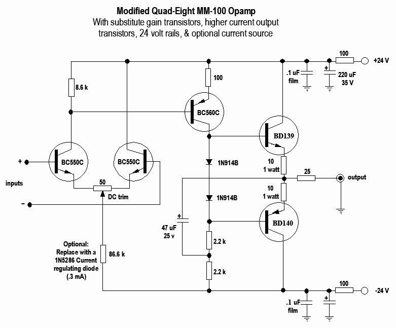
Getting in a bit over my head again but I took a few minutes to draw up this modification of the original modification of the Quad-Eight M-100 Opamp design. (I forget who drew up the original mod)
QE-M100-mod-1.jpg

I substituted some transistors & brought the rails down to a more common +/- 24 v. I have no idea if this would even work & be stable as I don't do Spice & haven't yet breadboarded this thing. I have seen the DC trimpot used on JFET input opamps but don't know how well it would work with BJT LTP. But it all seems in keeping with what NYDave was originally asking for: A few resistors & a few transistors. If anyone could mock this up in Spice, I'd be curious as to the outcome. Just an idea.

Skip
 
[quote author="Martin B. Kantola"][quote author="JohnRoberts"]In a basic fet follower using a resistor from source to ground to set the device operating current the Vg-s will change with signal swing causing distortion as this change in Vg-s subtracts from the signal at the source follower output. If you instead load the source with a current source the Vg-s is more constant so you eliminate that particular distortion source.[/quote]

Thanks for the explanation JR and Wavebourn, appreciate your patience with a beginner... My reason for asking is that I had a feeling that in this follower configuration (with enough current running and high enough voltage on the power rails) this distortion would be rather small. Is this a correct assumption?

Martin[/quote]

Yes, the smaller the change in Vgs with signal swing the lower the distortion.

JR
 
[quote author="JohnRoberts"]...

The 2sk170 was probably the part I was thinking of. I believe I used the single version of that (2sk117?) in my last phono pre and that was a very nice part. That was also 20+ years ago.... The really low noise bipolars I liked for mic preamps are now obsolete so I'm not surprised if other special interest parts fade away too as modern engineers are more inclined to use off the shelf IC solutions.

JR[/quote]

The SK170 is still supported but is a single FET. Linear Integrated Technology is also making their own version.
 
[quote author="bcarso"]

The SK170 is still supported but is a single FET. Linear Integrated Technology is also making their own version.[/quote]

My bad I was thinking of a dual version of the 117 and I'm too lazy to dig through my old papers to find a part number that may be obsolete now.

My past experiences with parts going obsolete inclines me to use mainstream parts whenever possible, however when exploring the limits of noise performance and such you are at the mercy of the fabs, and parts designed for higher volume markets.

JR
 
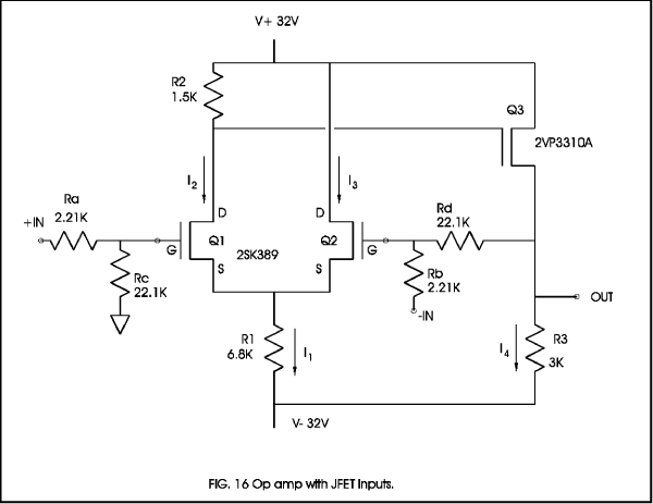
The Pass article was mentioned, here's one of the schematics from it.

diyopamp.gif


Is this something that would be worth developing further? The original text has some suggestions already of course, but where do you see the biggest limitations of something this simple?

Martin
 
the first thing you could do is use a simple current source at the differential pair.
helps a lot for cmrr and the gain goes up i think

at the output stage you also could use a current source. the advantage is that the capability to swing negative improves.
 
[quote author="Martin B. Kantola"]The Pass article was mentioned, here's one of the schematics from it. ...

Is this something that would be worth developing further? The original text has some suggestions already of course, but where do you see the biggest limitations of something this simple?

Martin[/quote]

It has very poor open-loop gain. The common-mode rejection is also poor. However, to the extent that the FETs have the canonical square-law characteristic, the residual distortions tend to be of relatively low-order. Some people like this.

And yes, LazyOne's current sources will improve matters. As the source for the input FETs the biggest effect will be on CMR, and at the output the gain will go up, although dependent on the load impedance---which includes the feedback network.
 
You might look at a vacuum tube opamp, and adapt from that.
The Tube Tech opamp is only 4 triodes, if I remember right.
 

Latest posts

Back
Top