single supply VU meter driver

GroupDIY Audio Forum

Help Support GroupDIY Audio Forum:

This site may earn a commission from merchant affiliate links, including eBay, Amazon, and others.
PRR said:
> Have I missed something?

This heat wave. Beastly sweaty, my abacus beads are slipping. Go with your numbers.

My wife w just reading to me about the heatwave in parts of continental Europe - temperatures up to 108 degress Fahrenheit (42 Celsius). Here in the UK it is mild and cool with sunny periods and showers. At other times, the weather men delight in telling us it is hotter here than in Athens. That's weather for you.

Cheers

Ian
 
zamproject said:
If you trust your ear for the global balance "real" Vu still usefull for 2tk main out ! they give you a great and quick view of your global energy coming out...
I agree if you record to tape, but for any digital media it's just a nice light-show.
I don't need any instrument to tell me how loud, my ears are enough*; I need a PPM to tell me how far I am for digital clipping, though.
* It would be different if I worked in film or TV, where there are stringent regulations that allow some manufacturers to continue to sell equipment when the music/recording market is dead.
 
While I haven't said this in this thread yet, mechanical VU meters are a legacy anachronism...  They were useful and SOTA at one time, but today pretty much useless for other than signal present.  Back in the day, users had to learn how to apply windage to VU readings for different sources. A VU meter on drums would be different than VU meter on vocal or bass.

There is merit in monitoring both peak metering to prevent path saturation, and average metering for relative loudness (while modern technology could make that loudness even more representative of human perception with weighting). 

For decades I have advocated displaying both peak and VU simultaneously. That provides even more data (crest factor) from comparing the difference between the two.

While in the past I have sold consoles with a full load of mechanical VU meters (the customer and his money are always right)  I challenge anybody to easily monitor all of them at the same time.  ::) (At least I added red peak LEDs so you could easily identify a hot channel.)

If you want your product to look old, mechanical VU meter eye candy will do that. If you want the meters to actually be useful, I prefer LED peak/ave (simultaneous).  There are mechanical peak (PPM) meters and I have even heard of two vane mechanical meters but they get a little funny to read. (and don't even put ave on the second vane, typically L/R or sum/difference).
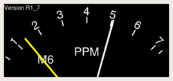
250px-Paqt_meter.m6.png


JR
 
So... I'm STILL working on it, and it doesn't work. Please, HELP! I'm desperate.

Could you have a look at this circuit I'm using after all the considerations in this thread? Is there anything wrong with it? Is there something I'm not seeing, or something missing? I have it wired, checked a thousand times, and it simply doesn't work AT ALL:
 

Attachments

  • VU_driver_complete.png
    VU_driver_complete.png
    24.6 KB · Views: 35
There is something else wrong. It looks to me like there is no feedback at all around the second TL072. Also there is no simulation ground reference for the first one.

Cheers

Ian
 
> It looks to me like there is no feedback at all around the second TL072

Meter current flows in R5, opamp reads this. No?

> no simulation ground reference for the first one.

I missed this.
 
WOW, guys. I'm really sorry to make you waste time with a wrong schematic. When I was drawing it yesterday, my wife started to rush me for going out, and I got the drawing wrong. But now I did a new version, and it reflects exactly how it's wired:

Works in simulation, but doesn't work in real life. I tried to substitute meter, and it doesn't change. Also tried to substitute opamp, and it doesn't change.  Checked all connections and it's all good.

??? ??? ???
 

Attachments

  • VU_driver_complete.png
    VU_driver_complete.png
    25.4 KB · Views: 33
rafafredd said:
Works in simulation, but doesn't work in real life. I tried to substitute meter, and it doesn't change. Also tried to substitute opamp, and it doesn't change.  Checked all connections and it's all good.
I don't know from sim program syntax, but are the +/- inputs of the same polarity?

Is that really 17 pico-amps at the meter? Must be a really sensitive meter.

Gene
 
rafafredd said:
Works in simulation, but doesn't work in real life. I tried to substitute meter, and it doesn't change. Also tried to substitute opamp, and it doesn't change.  Checked all connections and it's all good.
Use standard faultfinding techniques; follow the signal; is it correct at the output of the debal, is it correct at the input of the second stage, measure the voltage at all pins of the IC...the circuit is correct, so it's the implementation that's faulty.
 
opamp was oscillating badly. I changed the decoupling cap to a polyprop film type and it works great now.

Thanks for all.
 
PSU decouplig, near to the opamp V+pin. I was using a very old and very big ceramics cap, probably was bad... I replaced with a 100nF poly cap and it stoped oscillating.
 

Latest posts

Back
Top