Smart Circuits to learn from

GroupDIY Audio Forum

Help Support GroupDIY Audio Forum:

This site may earn a commission from merchant affiliate links, including eBay, Amazon, and others.

Rochey

Well-known member
White Market Member
Joined
Jul 2, 2004
Messages
2,697
Location
Dallas, TX - Formerly UK
Gents,

based on another thread, and some inputs from John, I thought I'd share some schematics that really cause me to scratch my head and admire the tricks done with cheap transistors! :)

The first is from an ongoing thread:
http://www.ka-electronics.com/images/pdf/Loftech_TS1.pdf

Top left hand corner. The designer did a stellar job of creating a 5V rail from the outputs of the transformer, wtihout burning watts in the regulator. A truly stellar job.


The other is a favourite of mine. Lucid GenX6 Studio clock generator and distributor. The tricks done with detection and user feedback, as well as the circuit around the TLC2932 is beautifully done.

http://www.symetrixaudio.com/kb/GENx6_sch.pdf


Care to share any of the schems you've found over the years that did some truly smart things?

Cheers

R
 
yup. i'll update my first post.

Still chewing on it. doing all I can to avoid putting it into spice! Trying to work it out.

Q20 basically sets a point that it's base needs to be 5.7V or higher before it sets the base of A06 to 5V, right?
Then if the Emmitter of A06 (input to regulator) is above 5.7V, it stops feeding the regulator.

What's really cooking my noggin is the impact of R111, R112 and R113. R111 shouldn't change the bias of R112 and R113, once they are charged. (by charged, I mean full wave rectified and smoothed).

Help me Obi-Wan-John-Roberts, your my only hope.
 
I'm not Obi but will try to answer  :)
IMO, R112 and 113 are used to set the switching point of Q19 and 20 to get cca 10V  at input of the reg. R11 is used for speed up of the transition of the Q20 (and Q19) state.
 
Rochey said:
yup. i'll update my first post.

Still chewing on it. doing all I can to avoid putting it into spice! Trying to work it out.
I'll have to figure it out again, but I recall in general how it worked.
Q20 basically sets a point that it's base needs to be 5.7V or higher before it sets the base of A06 to 5V, right?
Then if the Emmitter of A06 (input to regulator) is above 5.7V, it stops feeding the regulator.
OK, there is a little trapeze act about starting up, but we can ignore that because it starts up reliaibly.

Yes Q20 is the basic regulation comparator... The emitter of Q20 is tied to my free 5V voltage reference.  When the base of Q20 is high enough to turn on Q20 (5v+ a Vbe drop) is starves base current from Q19 to set the pre-regulated voltage (8-10V)
What's really cooking my noggin is the impact of R111, R112 and R113. R111 shouldn't change the bias of R112 and R113, once they are charged. (by charged, I mean full wave rectified and smoothed).

Help me Obi-Wan-John-Roberts, your my only hope.
If we first ignore R111, and just look at R112 and R113, they create a simple divider string to establish the pre-regulated voltage, this is straightforward.

The secret to R111 is that it is not fed from a smoothed DC but the rectified AC coming from the transformer winding through diodes, but with no reservoir cap at that node.  When the input diodes D36 and D17 are reverse biased R111 sits up around 5.5V, but as the transformer winding voltage rises pulling up R111, this has the effect of ramping down the pre-regulator voltage. In fact when Q20 senses that to has charged the pre-regulator cap to target voltage and  starts to turn on (and turn off Q19 ) the winding voltage jumps up as the current draw is released, causing R111 to increase the Q20 base drive even more for some snap action hysteresis, that keeps the transistors running cool and happy. 

Without the R111 positive feedback, Q19 would overheat and release it's smoke from trying to hold the pre-regulated voltage up for the full cycle dissipating a bunch of power.  There is ripple on C33 just like a diode connected reservoir cap as it must supply current between charging pulses.

JR

PS: If I was designing this today I would be tempted to use a switcher, but this was great for what it was and allowed me to pull a few hundred mA at 5V for the LED displays. Using my standard +/- 15V transformer that I already used in a half dozen SKUs at LOFT. I suspect using some modern mosfets in place of the bipolars and modern LDO regulators for the 5V I could have carved a bunch more power out of it...  I have though many times about revisiting that product using modern technology, but it's against my religion to sell any product that can be replicated with a smartphone app.  8)
 
Black Magic John, Black magic.

You said the winding voltage jumps up. I'm missing something in translation.

Amazingly elegant so far!!!
 
Rochey said:
Black Magic John, Black magic.

You said the winding voltage jumps up. I'm missing something in translation.

Amazingly elegant so far!!!

Transformer windings have a source impedance that looks like a small R in series with the winding. When the current draw from my pre-regualtor charging circuit falls off quickly, the voltage drop due to that current draw goes away too and the winding voltage jumps up, feeding through R111 to make it turn off even faster.

Not magic but nice "snap action" hysteresis....

JR

PS: This is why if you look at a transformer secondary with a scope the top of the sine wave gets flattened off, because of the current draw charging the reservoir caps.
 
> wtihout burning watts in the regulator.

Oh, that's nice.

> winding voltage jumps up. I'm missing something

When I turn-on a big load, my lights dim. When I turn it off, the lights go back to bright.

The exact amount depends on the length and fatnesses of my too-long power line from the street. But ANY power source wants to dip/rise with load/no-load.

(Some sources have accessory gizmos to reduce this: the generators at my local dam have series field coils which goose the juice when demand rises; we all know 7805 and better regulators. But a small transformer has a fairly reliable sag, and thus an un-sag.)
 
Speaking of transformers and winding impedance, here's a little known fact about power amps you might not know if you never manufactured them.

Transformer windings are generally copper wire with a positive temperature coefficient so a hot transformer will lose more voltage drop in the transformer windings due to higher resistance as the wire heats up, An amplifier that makes X watts when cold, will make <X watts when hot...  :(  Awkward when your customers like to test them after they are hot.
==========

I have two amplifier tricks that I never used but are kind of on topic. If you are familiar with class G/H power amps, they use a high voltage rail for making peak power, and an intermediate voltage rail to more efficiently make power for typical music playback.  The efficiency of these multi-rail amps depend a lot on the average power being demanded.

My amp trick #1 was to use a version of the synchronous rectification PS I used in my old Loftech TS-1 for the middle rail of a class G/H power amp and then tweak the intermediate rail voltage to maximize efficiency for the actual music playing , as it plays.  I was going to measure the heat sink temps for the high rail and mid rail power stage to force them to maximize efficiency.  This would also reduce the transformer cost since one secondary winding could serve both the high and mid rail. Another benefit is that the mid rail is drawing current away from the waveform peak so there are less wire losses in the primary (crude power factor correction). 

This is academic now that class D amps can deliver even better efficiency simpler and cheaper. So mental masturbation.

Amp trick #2 was a way to non-invasively compute the temperature of the transformer winding from the winding source impedance. As the transformer heats up and the winding impedance increases the charging waveform on the reservoir caps changes. This became academic as torroid transformers became more cost effective. They do not overheat as easily as EI core transformers. 

#3 a variant on #2 was to compare the current draw of a hot loudspeaker for a given voltage. As the speaker voice coil heats up, the winding resistance increases and it draws less current for a given drive voltage. Indirectly measuring the speaker voice coil temperature could be useful for smart protection.  This requires an amplifier with knowledge of it's current output (a feature in some high end install amps), while they mostly use the current feature to detect completely broken speakers at the theme park. 

ideas are cheap... but fun to chew on..

JR
 
I like  the smart "window" rectifier... and  getting it to work reliably with just two transistors is nice!

The circuit I'd like to mention for this thread is the side chain of the API 525, I saw it interesting how it changes the release behaviour with the frequency content. I don't have it now in the top of my head but I remember scratching my head for some time about that circuit.

JS
 
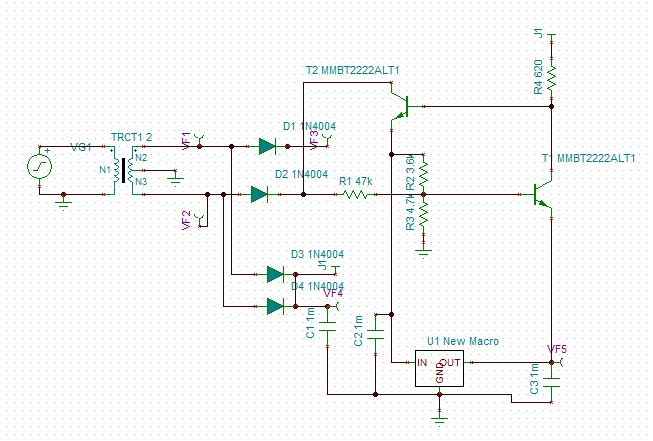
I can't, for the life of me, get this to simulate.

qgrIwWs.gif


what the heck am I missing?
 
Rochey said:
moamps said:

it all lit up like a christmas tree as soon as I added a load.

Whats the significance of the load? that the output cap can't discharge without the cap?
+VR generally don't sink current, only source it.

The base drive current when the pre-regulator is gated off gets shunted to the 5V rail. In use this is OK since that 5V rail is always drawing a lot more current than that, so the current isn't wasted. 

Using more modern parts I might have been able to use a mosfet switch that wouldn't need such a robust base drive current but this was done with common-cheap parts available 30 years ago. 

JR
 
Rochey said:
..Whats the significance of the load? that the output cap can't discharge without the cap?

Without a load, the current from the T1 goes INTO the regulator (more than 20mA in peaks). I believe your sim. software doesn't like that  :) .  Anyway, I don't like this circuit, and I will not recommend it for anything  except driving motors, LEDs and Vu meter bulbs. :)
 
moamps said:
Rochey said:
..Whats the significance of the load? that the output cap can't discharge without the cap?

Without a load, the current from the T1 goes INTO the regulator (more than 20mA in peaks). I believe your sim. software doesn't like that  :) .  Anyway, I don't like this circuit, and I will not recommend it for anything  except driving motors, LEDs and Vu meter bulbs. :)

I do not recommend this for new designs today.  It did what I needed it to do 30 years ago, get the power I needed at 5V out of my standard higher voltage transformer.  Without this trick circuit, or a switching power supply, I would have needed to source a different power transformer.

I still think this approach might have merit for generating a mid voltage rail for a class G/H power amp, since making the mid rail variable could improve amp efficiency, and power factor wrt mains current draw,  but even that is mooted by modern switchers, and class D audio amps.

So just an old curiosity...(like me).

JR
 
moamps said:
I don't like this circuit, and I will not recommend it for anything  except driving motors, LEDs and Vu meter bulbs. :)


My usage for it are Status LED's, driving a low power microcontroller and a few 5V relays.
 
Some interesting things came in my sim of that circuit (if anyone is following out of interest).

If I start the system with a load of 50Ohms or less (100mA), it fails to startup.  VOUT ends up at 1V or so.
However, if I start at 200Ohm, and reduce it to 50 while it's running, it's fine.

I guess I could always have a load switch after this circuit.

But I started scratching my head, wondering why the circuit wouldn't "start up" well under heavy load.
If the output never gets to 5V, then it'll struggle to start up, so I took my R4 and lowered it to 330 Ohms. That seemed to switch of T2 a little more to allow more current through.

I also get some more ripple at high current, as the capacitors discharge. I suspect increasing the rails from 100uF will help smooth that out.
 

Latest posts

Back
Top