Somewhat Different Mic Circuit

GroupDIY Audio Forum

Help Support GroupDIY Audio Forum:

This site may earn a commission from merchant affiliate links, including eBay, Amazon, and others.

Rossi

Well-known member
Joined
Dec 11, 2004
Messages
1,534
Location
Germany
Here's a little circuit I've come up with to cure the "Chinese disease", i.e. flat bass, murky mids, harsh treble.

It is built around the K67ish capsule response.

Here's the circuit:
[removed]

And this is the (simulated) response curve:
AH_plot.png


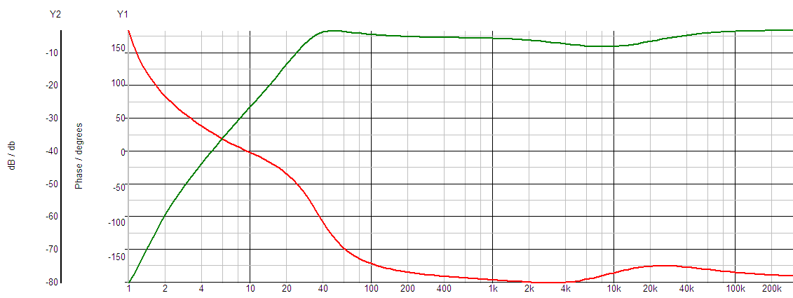
It works as advertized. I put this circuit in a SE Elecronics M1C mic. That's an obsolete model that looks like a TLM103, and now it sounds kinda similar, too. It is still on the bright side, the treble boost in the capsule is much larger than what I compensated for, but it isn't as harsh as it used to be. The stock circuit (which was total junk) had a fixed low cut filter, so the bass response, while not ultra deep (we don't want to overload that tiny tranny) is much better with the new circuit. It is very, very low noise, too. I left space for a small DC/DC-converter, but it is not really needed. The capsule is slightly above 1 inch and has a pretty high output, anyway.

Comments?


Note: This circuit is NOT public domain. Feel free to use it, if you want to build a mic or two for yourself. For anything else, contact me first.
 
Interesting idea. Is there possibly a resistor missing between the juntion of C2 and R4 and the capsule? It appears that the capacitor C2, as shown, will dump the capsule signal to ground.
 
See a little UM57 a little KM54 with two turn over points plate the grid gate to grid eq and gain control

2N3819?   Think about the drain to gate voltage and the Id you are running at, what is your gate leakage current due to impact-ionization current?
 
burdij said:
Interesting idea. Is there possibly a resistor missing between the juntion of C2 and R4 and the capsule? It appears that the capacitor C2, as shown, will dump the capsule signal to ground.

Nope, this works as shown. C2 is part of a double low pass filter for the polarization voltage. This is the kind of capsule hook up you'll find in lots of tube mics (some transistor, too).
 
Gus said:
See a little UM57 a little KM54 with two turn over points plate the grid gate to grid eq and gain control

Yes the transformer hook up is stolen from Gefell. It's supposed to accommodate the modest little tranny.
I didn't think about the KM54, I'll have to look that one up to see what you mean. But my idea was to use something more like a bell curve instead of a simple low pass. LD capsules don't have much to offer beyond 15K, and I didn't want to attenuate what little there is.

Gus said:
2N3819?  Think about the drain to gate voltage and the Id you are running at, what is your gate leakage current due to impact-ionization current?

I'm afraid that's beyond my abilities. All I can say is that this circuit seems to work fine. The actual voltages are pretty much the same as in the simulation. Had to pick R10 a tiny bit lower for the actual 3819 FET I used. Would you suggest a different FET?
 
burdij said:
Is there possibly a resistor missing between the juntion of C2 and R4 and the capsule? It appears that the capacitor C2, as shown, will dump the capsule signal to ground.

Looked odd to me too, but as I understand it the real life capsule is actually represented by two parts in the schematic (to make the simulation work I'm guessing?)

V1 (the signal voltage) could be in series with C1 (capsule capacitance) and not connected directly to ground. Or?

Martin
 
Yes that's how I represent the capsule. The real capsule is not grounded but floats slightly above 0V at the FET gate.

I've used other AC source hook-ups for the capsule in simulation, but this arrangement seems to work best.
 
I have a question regarding the connection point of the "Eq" network; R3C7 and R5C8 to the C2R4.

Namely - is this ONLY an equalization network OR is there some sort of a negative feedback involved? C7, C8 and C2 could be seen as a some sort of a capacitive divider, and there would be some sort of a NFB applied to the "cold" side of the capsule? //naivelly speaking...

I like simple spartanian circuits full of "dirty tricks"... they usually sound better when done "right"..
 
C2 R4 really hasn't much to do with the response. It is just to filter the polarization voltage (C2 R4 and C12 R6 are both low pass filters to get a clean DC voltage). Although it looks like the C2 does some low pass filtering for the capsule, too, it doesn't. If I remove C2, the simulation spits out the exact same curve.

R3 C/ and R5 C8 produce frequency dependent negative feedback (across the capsule back to the FET gate). The result is a soft treble roll off.
The Gefell-style transformer hook-up also produces some negative Feedback.
C5 produces a slight treble boost to bring the curve back up in the top octave.

One of the good things about this circuit is that it requires no large cap values (in the signal path), so you can easily use polyester, polypropylene or polysterene. It doesn't require a whole lot of space either, or any expensive parts. The NTE4 is about 10 Euros.
 
Rossi said:
I've used other AC source hook-ups for the capsule in simulation, but this arrangement seems to work best.

OK, cool. Guess it depends on the simulator, have you ever tried one where the capsule is represented as 2C-generator-2C? (two capacitors, one on each side of the signal generator).

Many thanks for sharing this, have some K67 capsules really haven't found any use for yet, lack of ideas for a better EQ network...

Martin
 
The way the xfmr is connected introduces some positive FB on the FET (sort like a Colpitts oscillator). The advantage of this arrangement is that it helps diminishing distortion in the xfmr. The drawback is FB is dependant on the impedance presented to the output; the lower the load impedance the higher the positive feedback.
Since you've already created the sim file, can you check the influence of load impedance on the frequency response?
 
I already did. I always check @ 2x 10k and 2x 100 ohms, which is somewhat higher and lower than any preamp you'd encounter in real life. The response doesn't change much except in level, of course.

Here's the plots. The top two are @ 2x 10k and @ 2x 600 ohms (which is my real life value) and the bottom one is @ 2x 100 ohms.

The level difference between 2x 10k and 2x 100 ohms is 5.2 dB. Which would suggest an output impedance slightly lower than 200 ohms, but in real life there are small copper losses, of course.

I haven't done any technical testing with the actual circuit, yet. Right now, I'm only listening and comparing with other mics.
 

Attachments

  • AH_load.png
    AH_load.png
    7.6 KB
Martin B. Kantola said:
Guess it depends on the simulator, have you ever tried one where the capsule is represented as 2C-generator-2C? (two capacitors, one on each side of the signal generator).


Hmm, do you mean a cap to each side of the + leg of the oscillator or one cap to the plus (representing the capsule) and a second one at the minus of the generator?

If I use the former approach with each cap double the capsule C, since they are in series (2x 130p for 65p), I get a slightly different response with a somewhat shallower 10k attenuation and a slightly stronger rise above that.

If I use the latter approach with an insanely large cap between the minus and ground (just to keep the oscillator from being DC grounded), I get the exact same response as with the grounded oscillator.
 
Rossi said:
If I use the former approach with each cap double the capsule C, since they are in series (2x 130p for 65p), I get a slightly different response with a somewhat shallower 10k attenuation and a slightly stronger rise above that.

Yep, exactly, this is what I had in mind. So it seems to work, kind of. But listening is always more important than trusting simulations :)

Martin
 
Hmm, not sure which way is more correct. Perhaps somebody else can shed a light on this.

Here's a few sound files. I used a Neumann TLM103 for comparison, I guess mostly because the SE mic looks so much like it.

Acoustic guitar:
http://www.andreashau.info/temp/SE_M1C_AH_NTE4.mp3
http://www.andreashau.info/temp/TLM103.mp3

As you'll hear, the mic noise is below my room noise (low noise computer and some birds outside)

I don't have a bass drum, so I used a cajon and put the mics close to the soundhole on the back.
You'll hear that the TLM has a deeper bass. But I'm quite pleased my modded mic did not crap out, despite the small tranny.
http://www.andreashau.info/temp/Cajon_AH_NTE4.mp3
http://www.andreashau.info/temp/Cajon_TLM103.mp3

So much for the sound files

I also tested with a very loud tamourine (Meinl Recording Tambourine). In fact the thing is so loud I won't play it without some ear protection. Banging it as hard as I could 12 inches from the capsule, you do hear some distortion, although I wouldn't say it totally buzzed out like some mics do at that distance. The TLM remained totally clean, even that close. At about 2 feet distance, my modded mic was about as clean as the TLM.

I also did some singing, which I'll spare you. As I said, the modded mic is still on the bright side, but I wouldn't say it's overly sibilant. The TLM has fuller mids, and a tighter cardioid pattern (the recording sounds drier). Well, a circuit won't change the capsule.
But the modded mic does not sound unpleasant, overall. It's not exactly a crooner's mic, but something more modern, pop-ish, and in your face.
 
I just noticed an error in the schematic: R2 should really be 22k, which gives a drain voltage of about 10V.
 
Hi Rossi,

Is it this mic?

http://4.bp.blogspot.com/_H8zTtRTkRPs/SLa-pVvOVcI/AAAAAAAAAE4/Xg8qDPDZ9s0/s1600-h/SEmic.jpg

I picked on up for next to nothing, but with stock capsule and circuit it is really bad. The body and hard case are quite nice, and it would be nice to find something to do with it. Might give this a try.

Thanks!

Stewart

 
Yes that's the one. The stock circuit is really total crap. I bought two of them; originally I wanted to use the bodies for two tube mics, but the interior turned out a bit small for that. Anyway, I put a Dale M7 in one of them, and it still sounded crap. The stock circuit is that bad. I had to modify it quite extensively to make the Dale capsule come to its full potential.

So I thought, why not give the SE capsule a chance in the other mic? I mean, if the stock circuit is bad enough to make a good Dale M7 capsule sound bad, it's possible the stock capsule is actually quite okay. And it is. So I came up with this circuit that takes care of the K87ish treble boost. The stock circuit actually does sport a HF filter, but other than that it is all wrong.
 

Latest posts

Back
Top