Hi Ssl Gurus,
I'm trying to rack 2x SSL 4000E channels from 1980 : SL611EW1080-TV-TR
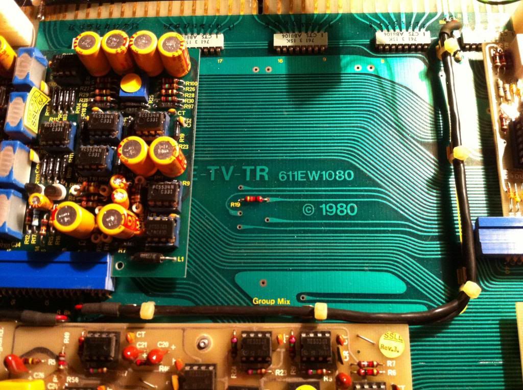
I'm cheking the pinout (611G version on my files) and I have a blurry idea what the 7x 20-ways pin blue connectors are for... TR and Multiplexing ?
They are labeled : S68 - S69 - S70 - S71 - S72 - S73
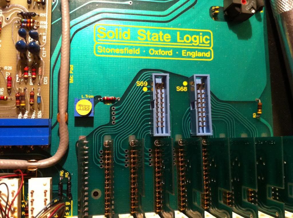
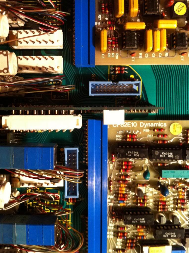
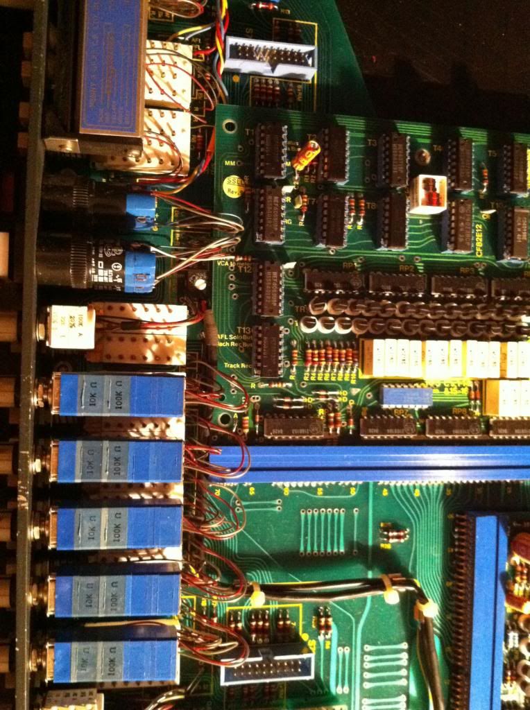
And S21E (I can find this one in the channel pinout)
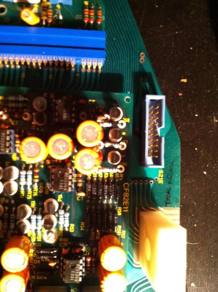
The motherboard is old enough to be built before MPX/Total Recall was completed so my questions are :
1/ Can I run the channel without CF82E03 card ( TR Multiplex Card ) nor the 7x 20-pins ribbon cables ?
What does the setting MPX/Bypass change ?
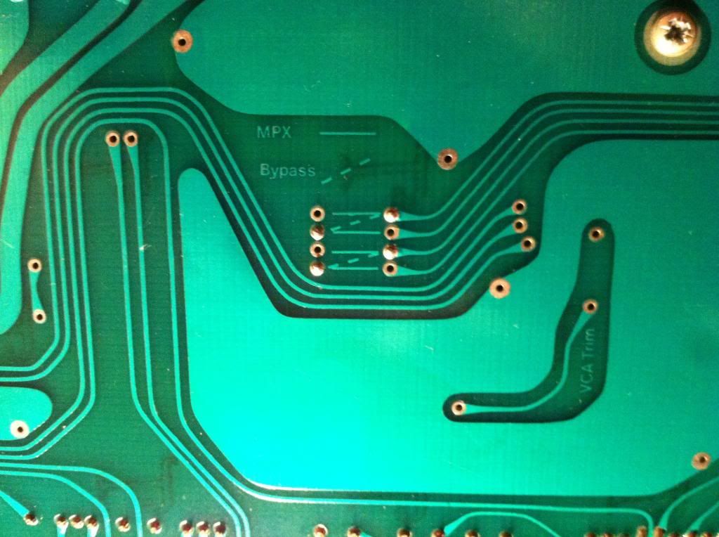
2/ Does someone could have the kindness to send me CF82E03 and CF82E12 schematics please ? Thanks in advance
3/ Just under the 82E03 TR card is the CF82E12, this card receives +18vdc (pin13), -18vdc (pin24) but can't find where goes the "ground" from pin12...
4/I also have a problem with no LED/no lights, every grounds coming from the leds seem to pass through S68-69-... 20pins connectors and as I have absolutely no 20pins ribbon cable connected, I guess my problem is there...or not.
5/PSU : my power supply made for this project is +18vdc -18vdc +12vdc +48vdc
+18vdc pins37,38,39
-18vdc pins48,49,50
+12vdc pins41,42
+48vdc pins34,35
Psu grounds Ov : 44,45,46
Did I miss something about the ground ?
6/Computer send and return (pins 28 and 29) : should I link them ?
7/When you switch a channel on without computer, what is the default mode (Record/Mix/VCA To Mon) ?
Thanks in advance for every tips or answers you could bring to this project.
Arno.
I'm trying to rack 2x SSL 4000E channels from 1980 : SL611EW1080-TV-TR

I'm cheking the pinout (611G version on my files) and I have a blurry idea what the 7x 20-ways pin blue connectors are for... TR and Multiplexing ?
They are labeled : S68 - S69 - S70 - S71 - S72 - S73


And S21E (I can find this one in the channel pinout)

The motherboard is old enough to be built before MPX/Total Recall was completed so my questions are :
1/ Can I run the channel without CF82E03 card ( TR Multiplex Card ) nor the 7x 20-pins ribbon cables ?
What does the setting MPX/Bypass change ?

2/ Does someone could have the kindness to send me CF82E03 and CF82E12 schematics please ? Thanks in advance
3/ Just under the 82E03 TR card is the CF82E12, this card receives +18vdc (pin13), -18vdc (pin24) but can't find where goes the "ground" from pin12...
4/I also have a problem with no LED/no lights, every grounds coming from the leds seem to pass through S68-69-... 20pins connectors and as I have absolutely no 20pins ribbon cable connected, I guess my problem is there...or not.
5/PSU : my power supply made for this project is +18vdc -18vdc +12vdc +48vdc
+18vdc pins37,38,39
-18vdc pins48,49,50
+12vdc pins41,42
+48vdc pins34,35
Psu grounds Ov : 44,45,46
Did I miss something about the ground ?
6/Computer send and return (pins 28 and 29) : should I link them ?
7/When you switch a channel on without computer, what is the default mode (Record/Mix/VCA To Mon) ?
Thanks in advance for every tips or answers you could bring to this project.
Arno.




![Electronics Soldering Iron Kit, [Upgraded] Soldering Iron 110V 90W LCD Digital Portable Soldering Kit 180-480℃(356-896℉), Welding Tool with ON/OFF Switch, Auto-sleep, Thermostatic Design](https://m.media-amazon.com/images/I/41gRDnlyfJS._SL500_.jpg)


