Stepped attenuator after Neumann V475-2 summing amp

GroupDIY Audio Forum

Help Support GroupDIY Audio Forum:

This site may earn a commission from merchant affiliate links, including eBay, Amazon, and others.

barthman.de

Well-known member
Joined
May 26, 2007
Messages
98
Location
Erfurt / Germany
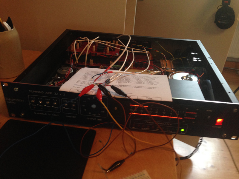
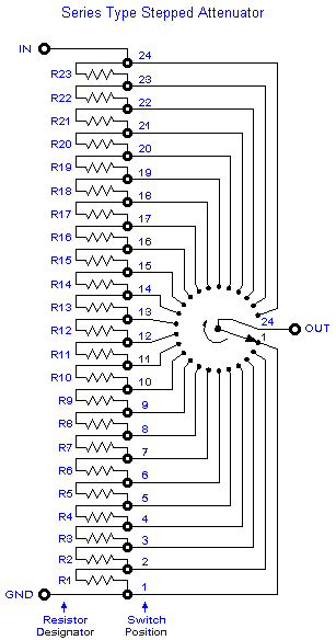
I want to  add a stepped attenuator after a Neumann V475-2 summing amp. I found the following schematic for a 1k attenuator:

sch_mv.gif


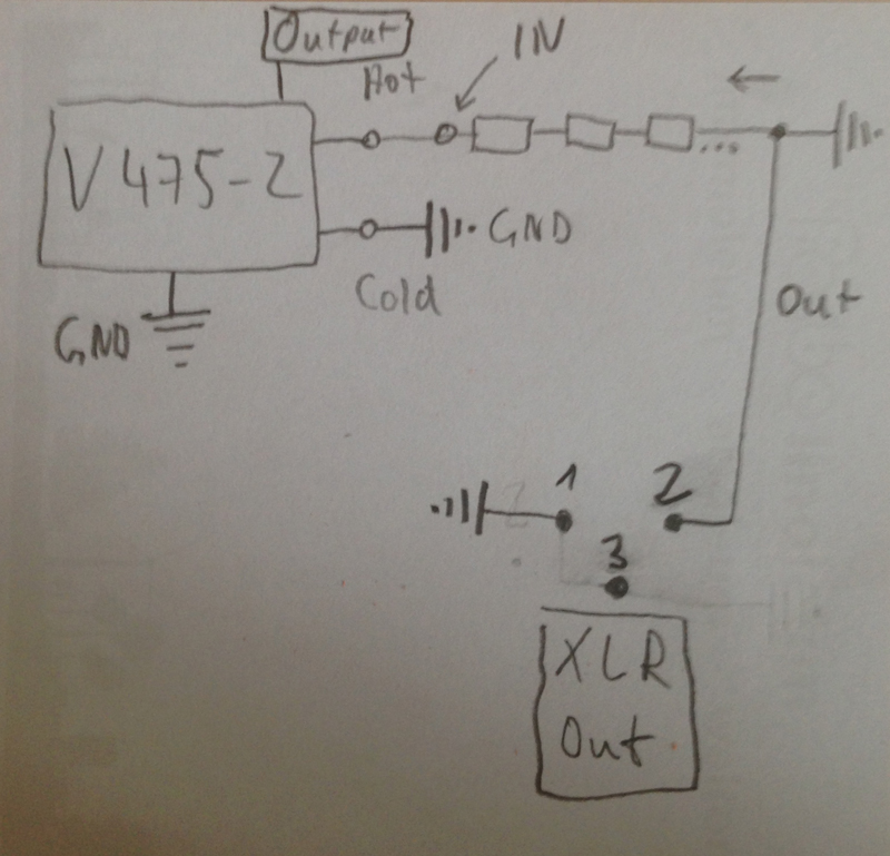
My question is: Have I add this between hot + ground only or have I add this with a stereo stepped switch between hot  + ground and cold + ground?
 
IN connects to hot input, GND connects to cold input.  Cold output (pin 3)  connects to GND and hot output (pin 2) connects to OUT. Pin 1 goes to chassis.

Cheers

Ian
 
ruffrecords said:
IN connects to hot input, GND connects to cold input.  Cold output (pin 3)  connects to GND and hot output (pin 2) connects to OUT. Pin 1 goes to chassis.

Hi Ian,

I had no luck - something is wrong or I don't understand.

At first: the V475-2 works fine without attenuator and I used your 1ksteppedATT pdf to build the attenuator with the resistor-settings for 1k attenuator.  I added the attenuator like described above and in addition I added it like shown in the picture with the same results:

-if I put XLR cold (3) to GND I have no level reduction
-if I don't connect it, I have less level (but less dB than in your description / ca. -6 db with 67R) and hum  :-[

Maybe the attenuator don't work with this type of summing amp?

V475_sa.jpg
 
[silent:arts] said:
Why pad the output?
However, it is a transformer balanced out, no need to actually ground anything.

OK that's the right way but I need a new setting of resistors because the 1k thing does not work. I have a 12 pos. Grayhill rotary switch. 10 values to reduce in steps of 2db to -20db. I found out that the max resistor must be nearly at 80k. How can I calculate the values exactly?

As compensation for the help a little photo from my test - setup  ;)

v475.jpg
 
 
barthman.de said:
[silent:arts] said:
Why pad the output?
However, it is a transformer balanced out, no need to actually ground anything.

OK that's the right way but I need a new setting of resistors because the 1k thing does not work. I have a 12 pos. Grayhill rotary switch. 10 values to reduce in steps of 2db to -20db. I found out that the max resistor must be nearly at 80k. How can I calculate the values exactly?

As compensation for the help a little photo from my test - setup  ;)

I played around with some resistors today and found out a new setting of resistors for a 1k attenuator between 206R and 21 R.  8)
 
barthman.de said:
OK that's the right way but I need a new setting of resistors because the 1k thing does not work.

And that is exactly the way I described it in my post. You say the 1K does not work. Can you elaborate?

Cheers

Ian
 
Your settings was fine, 1k too. I built R1 - R 12 of your excel sheet instead R13 - R23  :-[. If found it out because there was a calculator at the Internet. I calculated 206R/163R/130R/103R/82R/65R/51R/42R/32R/26R/21R.  User error  ;)

Btw: Thank you for helping me. Finished my summing amp today:

32 channels to Neumann V475-2
4 x Mono switches
Passive network output
Master insert
Stepped attenuator 2dB steps
RTW peak meter
phase correlation

Here some pics:
front2.jpg

front1.jpg

innen.jpg


Summing network and master insert:

summing_network.jpg

 
Back
Top