Stereo link in vintage Vari-Mu compressors

GroupDIY Audio Forum

Help Support GroupDIY Audio Forum:

This site may earn a commission from merchant affiliate links, including eBay, Amazon, and others.

truzz

Well-known member
Joined
Oct 25, 2009
Messages
47
Location
www
Hi,

Any idea on how to link the sidechains in old vari-mu units?
I'm particularly interested in linking 2 Sta-Level units.
Please post procedures, schematics, etc.

I know this topic has already been discussed for the past, but the link in the Vari-µ Meta page doesn't seem to be alive.

Thanks in advance.
 
Generally speaking I'm not sure it's a great idea. It would be a case of taking the most negative control voltage off C10 /R37 on each STA by using high conductance low leakage diode e.g. 1n459 or fdh333 (cathode towards C11) to feed a 10n 100V or so film smoothing capacitor on the centre tap of the input transformer between the grids of the 6386 to ground. You'll need something like a 1M resistor in parallel with the diode to discharge this smoothing cap, and to ensure the 6386's eventually self bias relative to 0V. For stereo you'd directly link the two 10n caps where the arrow points to "db comp" on the schematic. For dual mono you don't link them. It's yet another time constant, and probably not without some risk. Your mileage may seriously vary depending on how well matched your two STA's are, and also things like how this disrupts the existing R36 timing and biassing. Sorry I don't have a picture and I haven't done this on a real STA (only seen this on a home brew vari mu) so I can't tell you more than that.

Another far less intrusive option is to follow the example of the Fairchild 670. Build a simple L+R -> M+S input circuit. Compress Mid & Side completely separately without altering your 2 STA's at all. On output build a M+S -> L+R circuit (some DAW's already have this function built in as hardware or a software plugin, but there are plenty of examples online for it in hardware e.g. I got this just googling http://www.ka-electronics.com/Images/jpg/MS_163_Schematic_Small.JPG )

The two advantages of the second approach are:
i) you don't butcher your STA's (these are valuable pieces of vintage kit after all).
ii) you can build in the required pads/ level shifting in this converter (STA runs very hot compared to a modern DAW).
 
Find the Gates Dual limiter manual, the RCA BA-6C manual, Fairchild 670 manual, and the Collins 26U-2 manual for the variety of methods. 
 
its somewhere here in prodigy too, i think its under "another poor man 660 670" not the poor man's PCB tho...
 
Hi,
Thanks for the replies.

@MeToo2:
uhm, not sure I got this, probably a schematic re-drawn would be more useful to me (sorry).

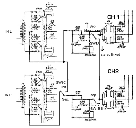
Surfing, I have found this picture, it seems redrawn from a UA 175 schematic. Would it be a solution?

vari-mu-stereo-link.gif
 
nope... there is a better way of doing it with diodes...
its in prodigy, just search...
 
The above picture basically works, but paralleled capacitance of the two separate time constant networks combine, basically resulting into doubled release time. It may or may not be a problem. As kambo hints, there is a way to prevent this with a simple diode trick, but unfortunately I don't have a schematic of that available that I could post right now.
 
Kingston said:
The above picture basically works, but paralleled capacitance of the two separate time constant networks combine, basically resulting into doubled release time.

Not if you look carefully. The diagram is not clear, but the switch poles are not all drawn in the same orientation. The TC circuit in the lower channel is disconnected in 'link' mode.

 
kambo said:
nope... there is a better way of doing it with diodes...
its in prodigy, just search...
uhm, I searched, but old posts don't have working image links, so hard to figure out.

MagnetoSound said:
Kingston said:
The above picture basically works, but paralleled capacitance of the two separate time constant networks combine, basically resulting into doubled release time.

Not if you look carefully. The diagram is not clear, but the switch poles are not all drawn in the same orientation. The TC circuit in the lower channel is disconnected in 'link' mode.
So the pic I posted is the working solution, or still needs the isolation dioes?
If yes, what's their correct place in that schematic?
 
truzz said:
So the pic I posted is the working solution, or still needs the isolation dioes?
If yes, what's their correct place in that schematic?
There's enough diodes already - the 6AL5's.
But I would worry about the two channels tracking. The balance control on each side provides some relative adjustment of each pair of input triodes - necessary indeed to avoid control voltage leakthrough. Getting satisfactory tracking between channels requires matching those pairs.
 
Hi all,

Trying to wrap my head around the best way to do a stereo link in my 670 clone. Their was no info in the manual etc just dont wanna blow this thing up any pointers would be greatly appreciated.

http://audio.kubarth.com/fairchild/670_Schematic.pdf

Thanks
 
Back
Top