I really dig the 1176's compression on drums, so I'm considering building enough of those to use them on every drum channel and -bus across the board. A typical session for me would then require 17 comps strapped across 4 stereo busses and 9 mono tracks.
I'm well aware that output transformers are the best and easiest way to add differential output, and come with an added sonic bonus in terms of harmonic distortion, LF saturation, funny gain/phase relationships and whatnot. The fact that they also cost quite a bit of money is enough for me to rule them out for now.
I also find that i rarely use metering besides the mixers meterbridge, so i could do away with those as well.
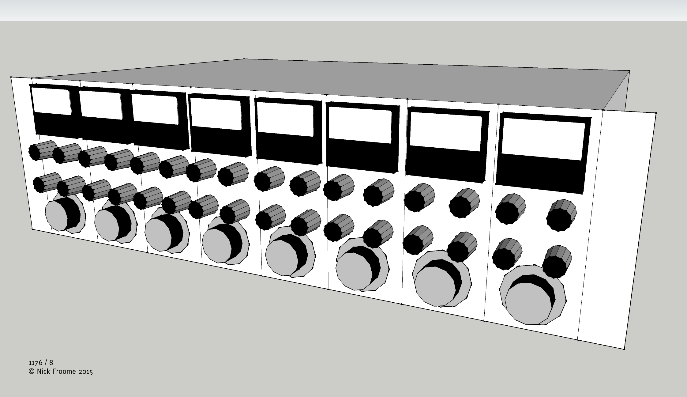
The goal of this project is to get as many compressors as possible - I'm thinking 6 or preferably 8 - into a 3 unit rack enclosure, in the cheapest manner possible.
All pots and switches should be board mounted to keep the wirejob to a minimum.
With the two most expensive parts of the circuit gone, my calculations say that I'll be able to build these for about $10-$12 per comp, including professional PCB manufacturing but excluding power supply circuitry.
And now for the fun part. I'll start with Gyraf's 1176 project, and strip down from there
Since the input is debalanced via op-amps, there's no reason why the output couldn't be rebalanced with op-amps. Essentially the last part of the circuit is just an amplifier with a gain of roughly 11dB and enough power to drive the output transformer.
Since the transformer is long gone, I'd figure I might as well replace the output amplifier circuit with op-amp based circuitry for the sake of simplicity.
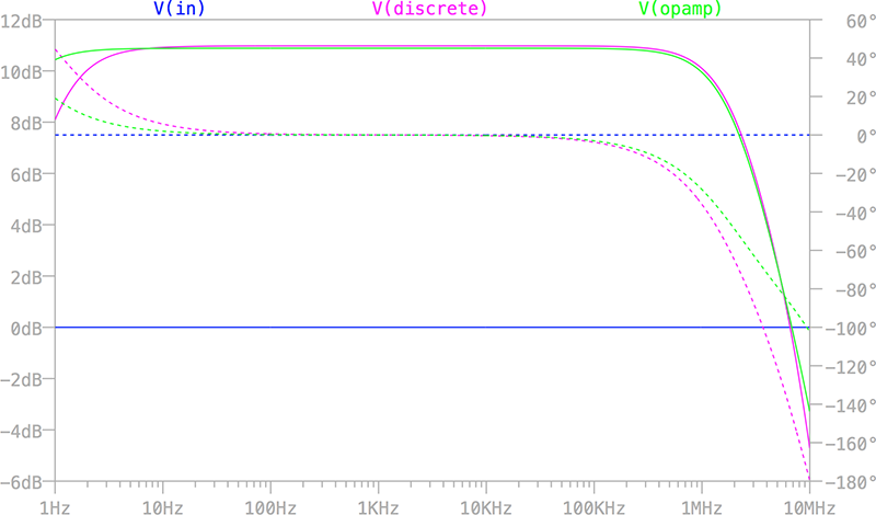
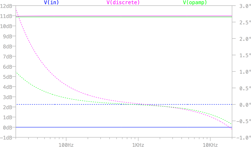
Simulations show that both circuits behave very linear from about 100Hz and well into MHz territory. For low frequencies the op-amp stage replacing the discrete output has even wider bandwidth and with that less phase change in the lowest audible frequencies - just about 1° at 20Hz compared to 3° at 20Hz with the discrete output stage.
With the input- and output circuitry taken care of, there's just the discrete GR-amplifier and input preamp circuits left, which will remain (relatively) untouched.
Here's the gain/phase plots from LTspice along with gyrafs schematic and my work in progress. Let me know if your eyes catch anything suspicious. Any thoughts and help is greatly appreciated!
/Hans
Output amp gain/phase @ 0Hz-10MHz:
Output amp gain/phase @ 20Hz-20KHz:
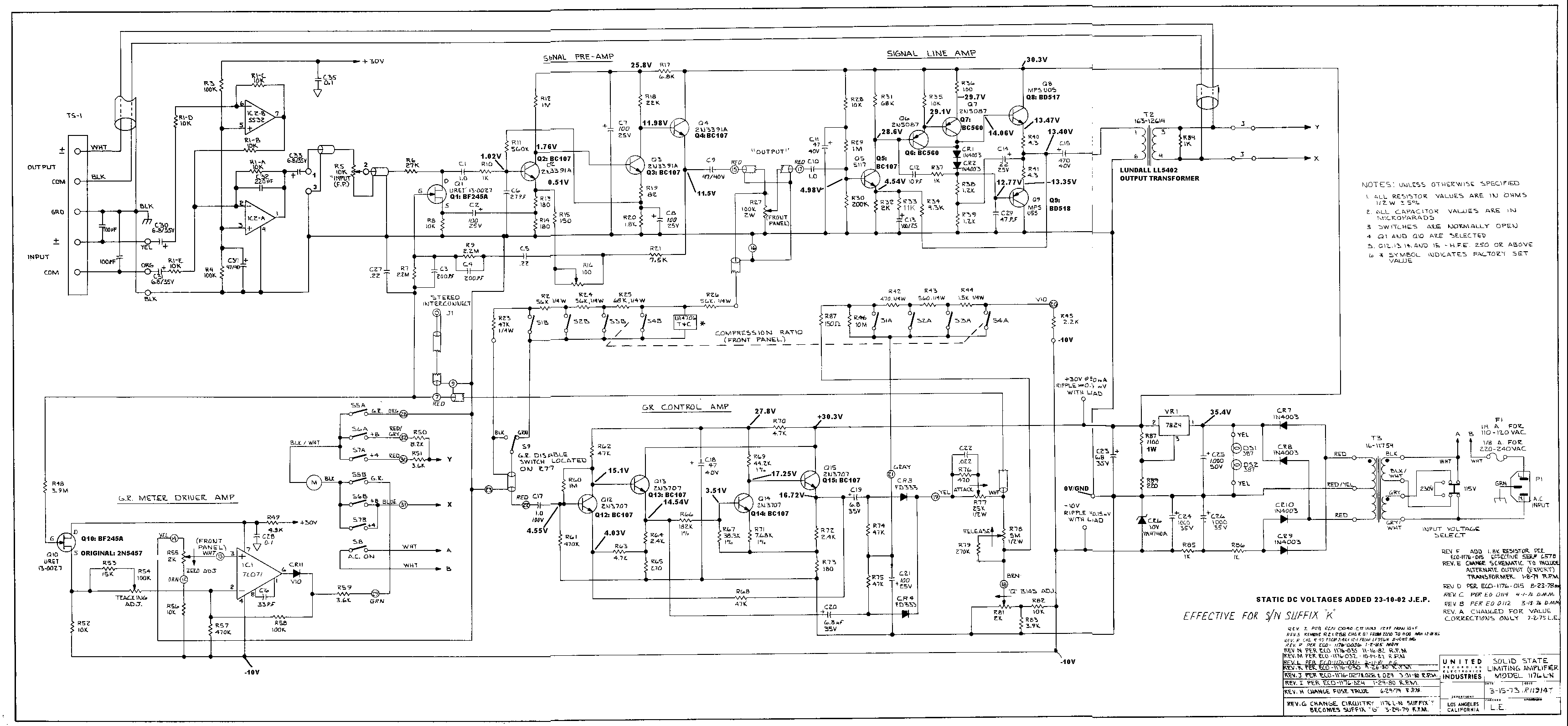
Original schematic:
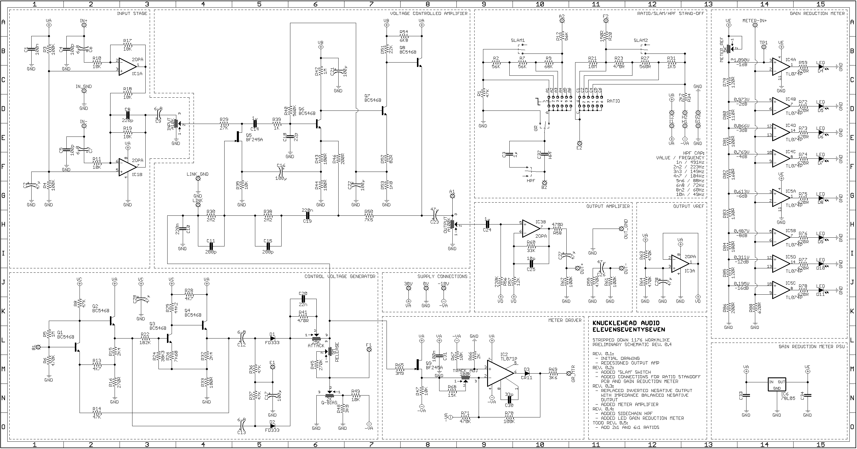
Working schematic in progress:
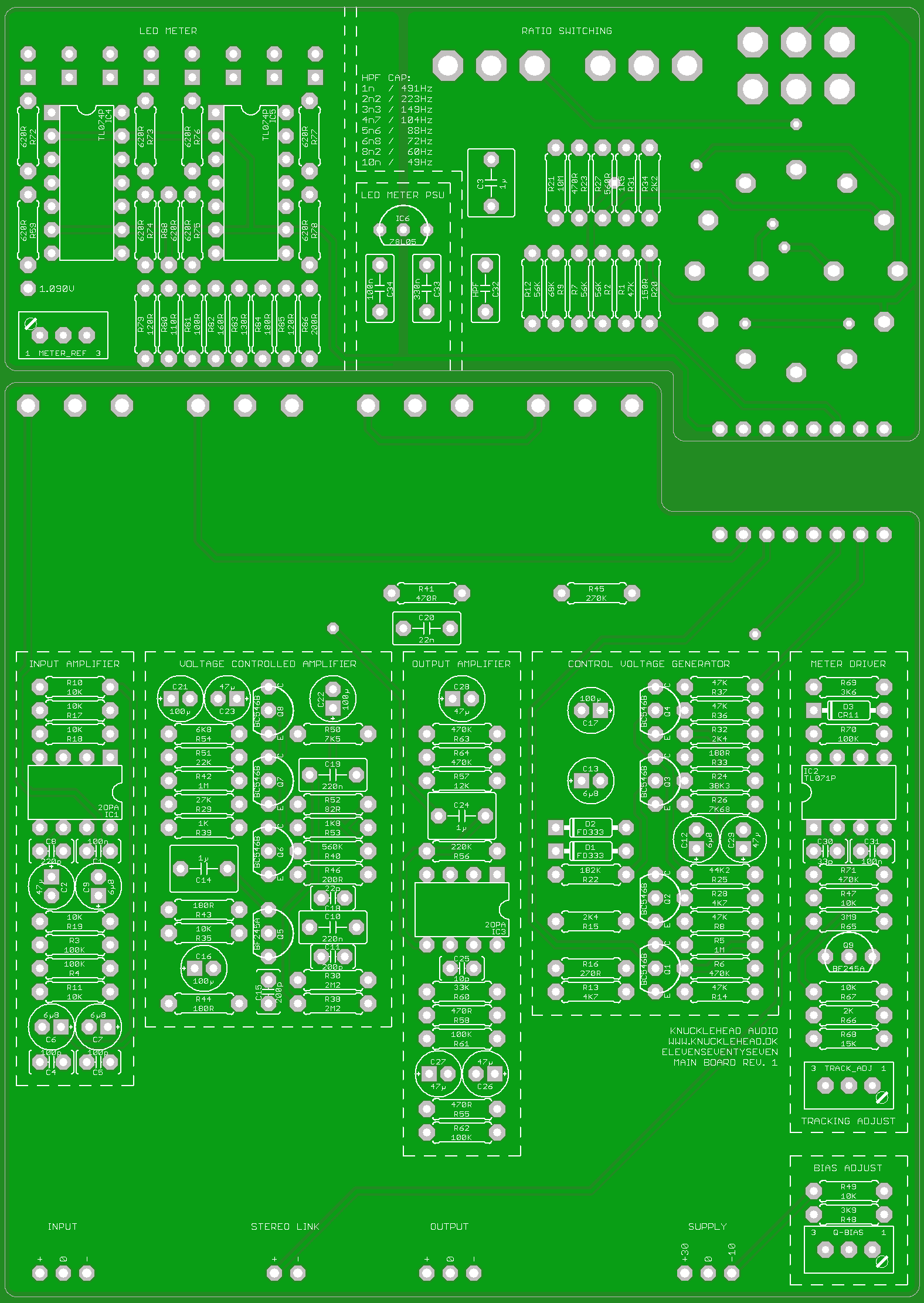
Boards top:
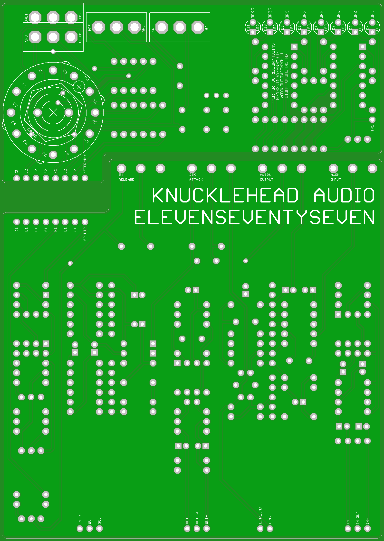
Boards bottom:
I'm well aware that output transformers are the best and easiest way to add differential output, and come with an added sonic bonus in terms of harmonic distortion, LF saturation, funny gain/phase relationships and whatnot. The fact that they also cost quite a bit of money is enough for me to rule them out for now.
I also find that i rarely use metering besides the mixers meterbridge, so i could do away with those as well.
The goal of this project is to get as many compressors as possible - I'm thinking 6 or preferably 8 - into a 3 unit rack enclosure, in the cheapest manner possible.
All pots and switches should be board mounted to keep the wirejob to a minimum.
With the two most expensive parts of the circuit gone, my calculations say that I'll be able to build these for about $10-$12 per comp, including professional PCB manufacturing but excluding power supply circuitry.
And now for the fun part. I'll start with Gyraf's 1176 project, and strip down from there
Since the input is debalanced via op-amps, there's no reason why the output couldn't be rebalanced with op-amps. Essentially the last part of the circuit is just an amplifier with a gain of roughly 11dB and enough power to drive the output transformer.
Since the transformer is long gone, I'd figure I might as well replace the output amplifier circuit with op-amp based circuitry for the sake of simplicity.
Simulations show that both circuits behave very linear from about 100Hz and well into MHz territory. For low frequencies the op-amp stage replacing the discrete output has even wider bandwidth and with that less phase change in the lowest audible frequencies - just about 1° at 20Hz compared to 3° at 20Hz with the discrete output stage.
With the input- and output circuitry taken care of, there's just the discrete GR-amplifier and input preamp circuits left, which will remain (relatively) untouched.
Here's the gain/phase plots from LTspice along with gyrafs schematic and my work in progress. Let me know if your eyes catch anything suspicious. Any thoughts and help is greatly appreciated!
/Hans
Output amp gain/phase @ 0Hz-10MHz:

Output amp gain/phase @ 20Hz-20KHz:

Original schematic:

Working schematic in progress:

Boards top:

Boards bottom:




![Electronics Soldering Iron Kit, [Upgraded] Soldering Iron 110V 90W LCD Digital Portable Soldering Kit 180-480℃(356-896℉), Welding Tool with ON/OFF Switch, Auto-sleep, Thermostatic Design](https://m.media-amazon.com/images/I/41gRDnlyfJS._SL500_.jpg)

