Stripped down transformerless 1176 workalike project

GroupDIY Audio Forum

Help Support GroupDIY Audio Forum:

This site may earn a commission from merchant affiliate links, including eBay, Amazon, and others.

Would you be interested in building something like this?

  • Yes

    Votes: 66 97.1%
  • No

    Votes: 2 2.9%

  • Total voters
    68
I've decided to go the impedance balanced output route. Saved an opamp that way, and it's not fuzzy about being run as an unbalanced output - just in case...
The meter amplifier fit nicely on the board as well. Everything in the meter amp square can just be omitted in case one doesn't want metering.
Schematic and board render has been updated in the first post. If you guys can spot any schematic errors, please let me know. I'll order a run of prototype boards from seeedstudio next monday, if everything goes according to plan.
 
By the way: Does anyone know if the diodes in the CV and meter amplifiers can be replaced with normal small-signal diodes (1N4148 or 1N914) without compromise?
 
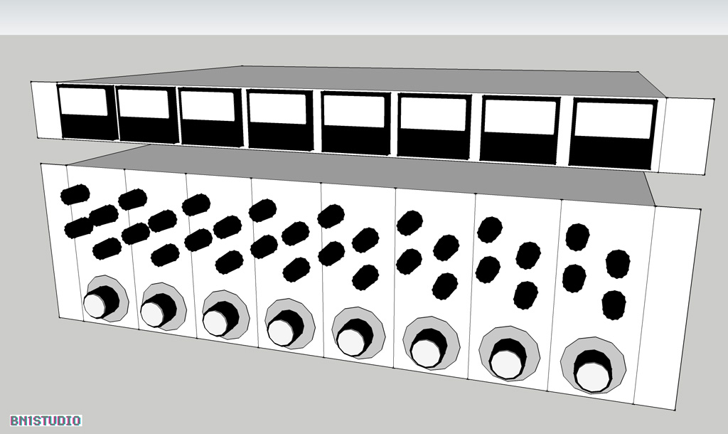
I looked again at panel dimensions and mocked up a panel with real knobs. It's pretty obvious that 3U doesn't give enough space for five controls, plus a meter, if the thing is to be comfortable to use

In fact, it makes me think 3U is an odd size for rackmount modules - 4 or 6U would be much better

Here is my revised version. I have moved the meters to a separate, optional, 1U meter bridge. I like it!

1176_8.version-4.jpg


Nick Froome
 
That's funny! I thought about that too.
"Whenever i feel like plunging the cash, that could be an option"-ish :D

I'll try and build one of these first without any metering, and then start tinkering with an LED-meter. It's still the least expensive option.
I've seen quite a few guys on this board ranting about LED-meters not having proper resolution, and not displaying true dB's, but recent production Neve and API modules utilize LED-meters, so i figure If it's good enough for them, it's definitely good enough for me too 8)
 
You could try to sub a BJT for a low-leakage CV diode (a C-B junction of a BC550 for example).

BTW if you are doing "stripping", why are you sticking with the original dicrete CV amp? A two-opamp sub would do just fine. From the top of my head, the discrete job is at 5.5dB gain or so (but not entirely symmetrical).

That would bring down the complexity quite a bit.
 
tv said:
You could try to sub a BJT for a low-leakage CV diode (a C-B junction of a BC550 for example).

Yes! I don't know why i didn't think of that. If it's the low leakage thing that's important in this application, either a BJT or a MOSFET in diode configuration should work great.

tv said:
BTW if you are doing "stripping", why are you sticking with the original dicrete CV amp? A two-opamp sub would do just fine. From the top of my head, the discrete job is at 5.5dB gain or so (but not entirely symmetrical).

My idea was to stick with the original circuit where it mattered the most.
I haven't simulated the behavior of the CV amplifier, but i suspect it introduces some specific non-linearities, that are crucial in order to maintain as much of the 1176 sound as possible.

I've only had an introduction course in control theory, mu thoughts are:
If you mess with the regulating curcuit, you mess with all sorts of funny stuff - including the distortion imposed on the signal as a result of the regulation, and we wouldn't want to mess with that. Would we? ;)

tv said:
That would bring down the complexity quite a bit.

Replacing the entire discrete circuitry with op-amps would be a fun project to do. That's up next ;) It would make an extremely easy build i guess...
By stripped down i mostly meant getting rid of transformers and moving coil meters. I probably should have named the thread "Increasing 1176 cost effectiveness while retaining as much of the original sound as possible" instead :D
 
BJTs are in T092 version much more cost-effective compared to mosfets.

I had a plan to do an all-opamp version of '76 (2x5532 + 074) with 99% of the design stuff fully sorted out, but never went with it to the final stage. It's easy though.

I used sort-of-similar (more in API525 manner) squashers in 80's. I still have two of these PCBs somewhere. Perhaps I liked these more than the '76 way of doing things.
 
Did I use FETs in a FET compressor? Yes.

Forum member Igor did a slightly more elaborate "opamp" conversion a couple of years ago. So you can peruse his basic schematic and "plug-and-play" your component values. With use of a simulator, it should only take an afternoon to have a fully working schematic.

http://groupdiy.com/index.php?topic=40009.0 (look for MAIN SCH in the first post)

My version was a bit different from the above and used some non-trivial tricks, but it's all there in the ballpark.
 
grrrunge said:
I probably should have named the thread "Increasing 1176 cost effectiveness while retaining as much of the original sound as possible" instead :D

I think you're spot-on there. I don't know how the 1176 does what it does, but if you swopped the FET for a THAT VCA, and the SC circuit for op-amps, I suspect it wouldn't be an 1176

Nick Froome
 
Very interesting project! Can't wait to see it come to life... Good luck on the design.
Do you already have a working unit? If yes, how does it sound compare to a "full" 1176???

Ben
 
I've decided to add LED-meters to my own build anyway. I figured that by extending the switch PCB to be the same height as the main PCB, i should be able to fit a sidechain high pass filter and an LED-meter on it as well. No extra wiring and all that :) Just gotta do some more routing...
Here's a true-to-scale mockup of the 8 channels on a 3U front panel.
1176_frontpanel.jpg
 
evilcat said:
Do you already have a working unit? If yes, how does it sound compare to a "full" 1176???
Nope, I'm still in the design phase.
It would be quite fun if one of the studios here in Copenhagen had an original 1176 i could compare it to, once it's up and running.
 
I updated the schematic to reflect my latest changes. Board layout is nearly finished (again :p).
I also just found this:
dmnieto said:
I did keep the 1:2 myself...

You just need to split the resistors on the 4:1 ration on each of the series and wire the intermediate position to the additional switch position=> substitute the 150 for a 68then 82 ohm and the 47k in 20K then 27K
2:1 and 6:1 ratios would be a nice-to-have addition. After all, there's two unused positions sitting on that switch, looking for a job ;)
Any info out there on obtaining 6:1?
 
grrrunge said:
I've decided to add LED-meters to my own build anyway. I figured that by extending the switch PCB to be the same height as the main PCB, i should be able to fit a sidechain high pass filter and an LED-meter on it as well. No extra wiring and all that :) Just gotta do some more routing...
Here's a true-to-scale mockup of the 8 channels on a 3U front panel.
1176_frontpanel.jpg

That's great you added the HPF, it's really an important feature I think.
Does the bypass a true one? It would be great rather than the "GR Off" of the original.
 
I updated the board layout render in the first post :) check it out, and let me know what you think.
I'll save the 2:1 and 6:1 feature for rev. 2, as I've got enough going on that board already.
All i need now is to get over the weekend, and I'm ready for prototyping!

evilcat said:
Does the bypass a true one? It would be great rather than the "GR Off" of the original.

Nope, bypass is done like in the original unit.
 
I'm really interested to see how this turns out. I imagine possibly putting 4 into an enclosure with one VU meter that is swappable between channels.
 

Latest posts

Back
Top