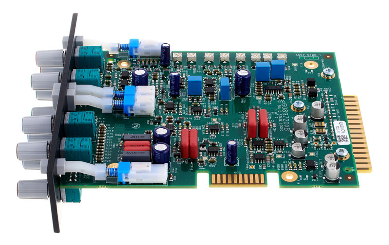
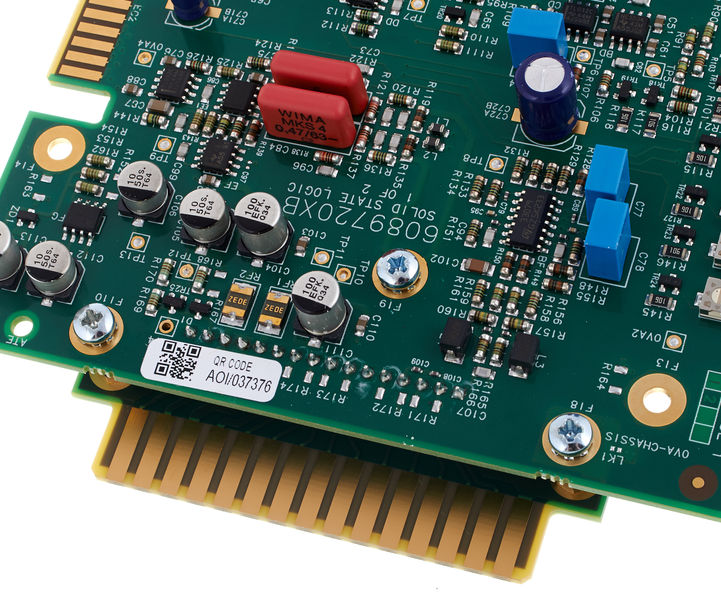
Update: The boards for the first prototype have arrived...

---
I’m building a API 500 series clone of the channel EQ from the Studer 900 mixer. I had the opportunity to play around with a Studer 900 desk a few years back and building this EQ has been on my todo list ever since.
As other Studer designs this is an active EQ and as I recall it, an exceptionally smooth and musical sounding one, even at extreme settings. I’m still trying to wrap my head around the finer details of the design, but it appears to be a Multi Feedback Filter of some sort (perhaps people smarter than me can comment).
The EQ has four bands with gain and frequency pots. HF and LF bands can be switched between shelf and bell, while HMF and LMF band have selectable high/low Q. The gain is +/- 15 dB for all bands and I intend to use pots with centre detent for these.
I added a line receiver and driver from THAT Corp for balanced in and out. Nothing special here (I took the circuit straight out of the data sheet) but it should outperform most other electronic solutions. I thought about using Lundahl transformers instead but I somehow doubt the benefit would justify the cost. I might do a listening test once I have the first prototype built though.
If everything works out as planned, I will be selling these both as assembled units and DIY kits. I will post in the White Market when that time comes but until then, I will be sharing my progress in this thread.
So far, I have redrawn the circuit in Kicad and simulated it in Spice. Next step is to design the first version of the PCB and order a few pieces for prototyping.
I have attached the redrawn schematic to this post.
/Rasmus


![Electronics Soldering Iron Kit, [Upgraded] Soldering Iron 110V 90W LCD Digital Portable Soldering Kit 180-480℃(356-896℉), Welding Tool with ON/OFF Switch, Auto-sleep, Thermostatic Design](https://m.media-amazon.com/images/I/41gRDnlyfJS._SL500_.jpg)


