Super Simple Opto comp design - ELOP-inspired

GroupDIY Audio Forum

Help Support GroupDIY Audio Forum:

This site may earn a commission from merchant affiliate links, including eBay, Amazon, and others.
[quote author="PRR"]But note that dividers in general ARE "limiter gain cells". Here you have a 2-part $6.13 divider (opto and resistor), and you are working your way around to a 30+-part measurement plan. You will have more solder, and probably more money, in the metering than the audio itself. Is that wrong? No! More meters! But when you go way overboard on one side, it is worth thinking about the Total Box and if money/effort may be getting thin someplace it matters.
...
Close and cheap often trumps precise and fussy.[/quote]

Great answer, PRR, thank you. I was coming around to the simple/cheap side of things after a couple frustrating days at the bench, trying for something precise and fussy...

I did go and look around at some voltage dividers (the multiplier w/feedback loop approach), and quickly said, hell no, not for this.

I will need to order some new parts to try the split LDR approach you describe. It definitely sounds like the most elegant way to incorporate a VU meter. I currently have the VTL5C2 parts, but those just have a single LDR cell.

For now, I'm planning to finish this circuit with a really simple LED indicator, to increase brightness as compression increases. It'll get fed from a point post-sidechain filter. I may drive the LED directly off the LM386, or buffer it so I can include a little RC circuit to simulate the 500ms release time of the VTL5C2 cell.

Another change in the works: moving the threshold pot to the output of the LM386. This will allow using the 386 for an audio output, as previously discussed here. Also, the 386 has 50K input impedance, and I've currently got a 100K pot across that, and I think it's doing something weird to the level near the top of the pot's throw (it's either that, or some kind of opamp/vactrol saturation, but there's some weird level change there). So the threshold pot will get moved to after the 386, and will likely need to be changed to a smaller resistance value.

There are a few other things to play with, and I'll post a revised schematic of the comp when it's all working right.

Oh, and I agree, the insight gained from all this mucking about on the bench has been valuable. I've been building stuff for years, but this is my first time getting this down and dirty with the design portion.

cheers,
Leigh
 
[quote author="leigh"]Another change in the works: moving the threshold pot to the output of the LM386. This will allow using the 386 for an audio output, as previously discussed here. Also, the 386 has 50K input impedance, and I've currently got a 100K pot across that, and I think it's doing something weird to the level near the top of the pot's throw (it's either that, or some kind of opamp/vactrol saturation, but there's some weird level change there). So the threshold pot will get moved to after the 386, and will likely need to be changed to a smaller resistance value.[/quote]

Made this change today, but I'm non-plussed about it. The 386's output is crunchy, at any compression threshold setting, so I wouldn't choose to use that as an audio output.

Also, I couldn't find a good pot to use after the 386... a linear 10K worked OK, but most of the action was toward the top of the dial. An audio-taper 10K worked terribly, since all of the threshold action was in the top 5% of the dial. So I guess that means a reverse-audio taper would work better, or I could just reverse the outer lugs of the audio taper pot and mark the control as backwards... but I don't like counter-intuitive controls in the studio.

So, I may move the threshold control to back in front of the 386, but keep the change from a 100K to a 10K pot. That way, the pot won't interact in that weird way with the chip's 50K input impedance.

Leigh
 
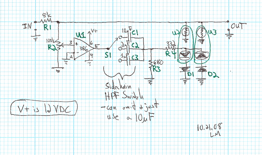
Here's an issue I can't quite get my head around. In this circuit, the sidechain's HPF is formed by the RC combo of R3 and C1-C3 (selected by switch).

SSOPTO.gif


When the voltage at that point is low, and the LEDs are not conducting yet, then the normal RC circuit math is fine for figuring the HPF's rolloff frequency. [ 1 / (2 pi RC) ]

However, once the LED's are conducting, above say one volt (for example's sake), then you've got R4 and the LED's also forming a path to ground. R3, at 680 ohms, is no longer the only R value to plug into the equation.

So this leads me to conclude that the rolloff freq of the HPF will be dependent upon the signal amplitude, and would even be changing on individual waveform peaks.

I found this chart that shows some values for LED impedance - the exact values not being important, the phenomenon of changing impedance with current being the point:

http://www.automotivedesignline.com/howto/201802180 (scroll down a touch for the graph - it was too huge an image to include inline here)

So... I can run some frequency response curves at different volumes to check the real-world response of this HPF. However, I'm thinking that, for stable filter rolloff points, the filter will need to be buffered from the LEDs...?

Either that, or, lower the value of R3 so it always dominates the response. If that graph is to be believed, however, that would mean lowering R3 to about one ohm (since the LED's need to take current up to 20mA or so) - which would be too small a load even for the mighty LM386.
 
[quote author="PRR"]The real dumb yet very elegant meter for opto-compresser is: use two LDRs from the same batch. Shine the same light on both. In the mid-range of light, their absolute values will be different but their change of value will track pretty-much. So you feed audio to one, check that it limits. Measuring its audio output won't tell you the compression because the input is unknown. So you get a 1V DC source (the opto-R does DC same as AC/audio), and a 1V meter, with the second opto between. At zero limiting the second opto does zero reduction, meter shows 1V. When the audio opto is limiting, the DC opto will reduce the 1V DC in a similar proportion...[/quote]

I was planning to go this route, and order some of the split-cell Vactrols (PerkinElmer VTL5C2/2). However, it would change the sound around of the compressor, since the VTL5C2 has a 500ms release time, while the VTL5C2/2 has a 150ms release time. 'Course, could lengthen that with a release circuit, but that means converting to a DC control voltage, and all that other business, and the "Super Simple" part is gone.

FYI, here's an overview datasheet of the PerkinElmer Vactrols, with a chart for easy comparison:

http://optoelectronics.perkinelmer.com/content/datasheets/dts_opticalisolators.pdf
 
[quote author="nickt"]Just a dumb suggestion what about putting the HPF before the 386? I guess that would mess with the actual signal?[/quote]

Yeah, that's what I was suggesting by "buffering the filter from the LEDs" - the 386 would be that buffer.

Sidechain path would go something like:
input -> TL071 (or other JFET-input chip) -> 10k attenuator pot -> HPF filter -> LM386 -> LEDs

BUT then you've complicated the design. I will do some real-world testing to see if it's worth it.

cheers,
Leigh
 
> the rolloff freq of the HPF will be dependent upon the signal amplitude

Not sure why you need a HPF (except to lose the '386's DC offset). Specially since your suggested 10uFd+680R is 25Hz, or essentially the whole audio range.

The LEDs will go to few-Ohm dynamic impedance, yes; but you have 332 ohms in series. Assume 30R LED impedance, 680||362= 236 ohm effective load, 78Hz HPF. On many musical sources, there won't be much difference.

That also explains this:

> audio-taper 10K worked terribly

A 680-238 ohm load is a poor fit for a 10K pot. The center of a linear 10K is 2500 ohms from both ends. Load it in <680R, it sags bad. You have to turn-up near "9" to get pot resistance down below 1K, not-large compared to 680. On a Audio taper this is more like "9.5", very twitchy.

IIRC I used 500R pots.

And in general, you do not like to put filters or pots at "power loads". Power load impedance may be low and often varies a lot. And anything bigger than an LED needs so much power you don't like to waste any.

> some of the split-cell Vactrols

You are correct that the spec-sheet speeds differ. I've never felt the spec-sheet number applied to audio limiters. See here:
34sigib.gif


Same cell. Same drive. Change the series resistor. Timing changes significantly.

If you have the 1-cell VTLs, want something to work, just add a panel LED in series with the VTL LED. The relative brightness and rhythm of the blink says a lot without numbers.
 
[quote author="PRR"]Not sure why you need a HPF (except to lose the '386's DC offset). Specially since your suggested 10uFd+680R is 25Hz, or essentially the whole audio range.[/quote]

The HPF on the sidechain is optional, sure, but I have been liking it on compressors lately. I was shooting for a 3-way switch: full range, 100Hz, and 200Hz. Will have to redo the cap values once I finish reworking the rest of everything else here....

[quote author="PRR"]The LEDs will go to few-Ohm dynamic impedance, yes; but you have 332 ohms in series. Assume 30R LED impedance, 680||362= 236 ohm effective load, 78Hz HPF. On many musical sources, there won't be much difference.[/quote]

Sometimes I can be so close... but just not put two and two together. I had even reasoned out the fact that R4 was part of the path to ground, but then I forgot to include it in my calculations. Sorry, and thanks.

With the value of the threshold pot, I figured it would need to be smaller, and your reasoning helps to clarify why.

[quote author="PRR"]And in general, you do not like to put filters or pots at "power loads". Power load impedance may be low and often varies a lot. And anything bigger than an LED needs so much power you don't like to waste any.[/quote]

Yes, that makes perfect sense as a rule of thumb. I will add it to the mental file.

[quote author="PRR"]You are correct that the spec-sheet speeds differ. I've never felt the spec-sheet number applied to audio limiters. See here...

Same cell. Same drive. Change the series resistor. Timing changes significantly.[/quote]

At first I thought you meant R4, the series current-limiting resistor, but I believe you mean R1, the series audio resistor. Again, great insight - I had thought of R1 as just changing the compression ratio/slope, but I see how that's directly tied in with the timing too. That also helps explain why, with R1 at 5K, I can get a bit of drum "pumping" style compression when hitting it hard, even though a 500ms release time should be too slow to get that pumping sound.

[quote author="PRR"]If you have the 1-cell VTLs, want something to work, just add a panel LED in series with the VTL LED. The relative brightness and rhythm of the blink says a lot without numbers.[/quote]

For the Super Simple design, that's what's I'm strongly leaning towards - either that or no metering.

However, I was thinking of putting the panel LED in parallel with the Vactrol LEDs, so that it didn't add to the LEDs' voltage drops and play with the threshold. If I did put an LED in series with the Vactrols, I would use a dual element one, so that both the Vactrol LEDs would have the same voltage drop added to them.

I plan on knocking out a revised version of the Super Simple Opto this week, keeping parts count to a bare minimum, and then move onto a slightly more complex design (with makeup gain and metering) after that.

Thanks again for all the insight here. It's been an immeasurable help.

Leigh
 
> that or no metering.

Disagree. You should know what you are doing to the audio. Tone control knobs should have pointers. Things that overload should have meters. Dynamic effects should have indicators.

In my world, any limiting on solo concert piano is a disaster. My goal (at least on low dynamic range tape) might be 1dB-2dB limiting on 1 or 2 notes in the whole piece. OTOH, my goal on young jazz musicians might be rather deep limiting through the drum solo, steady light limiting on ensemble passages, so I can bring-up the under-power solos.

> putting the panel LED in parallel with the Vactrol LEDs, so that it didn't add to the LEDs' voltage drops

Won't work great. LEDs are nearly constant voltage. Maybe zero light at 1.5V and full-bright at 1.7V. Or another LED (especially another color) might be 1.8V-2.0V.

You may get away with it in a simple limiter, especially with separate and significant series resistors for each LED. The actual LED action is all overload and idle, blip blip blip. This contrasts to a rectifier and filtered sidechain where the LED signal may be drifting 1.55V-1.6V-1.57V pretty stable.

Even if you series them, so the pass the same current (brightness is pretty proportional to current), there is the difference between photo-R sensitivity and eye sensitivity. Some of the Vactols (type 10) used with large series audio resistor will give significant limiting at 0.1mA. In a bright booth, you may not notice 0.1mA on a panel LED. OTOH a less eager photo-R or lower audio impedance may need 5mA-10ma for small limiting, and in a dark studio that can look quite bright. Obviously within limits you learn what the blinking LED is trying to tell you, but be aware that it isn't "truth". It is just a buttload cheaper than a meter.
 
[quote author="leigh"]I plan on knocking out a revised version of the Super Simple Opto this week, keeping parts count to a bare minimum, and then move onto a slightly more complex design (with makeup gain and metering) after that.[/quote]

FYI - The low parts-count variation is now up here:

http://www.groupdiy.com/index.php?topic=366276
 
flaheu said:
Hi,

I was reading the thread, and found that the link gives an error  ???

Yeah, that would be on account of, when Ethan updated the message board software, the URLs for the board also got changed. So all many old links will be broken now... is this globally fixable, Ethan?

Anyways, the thread in question can now be found here:
http://www.groupdiy.com/index.php?topic=30196.0
 
How about this? (a "concept")

Simplicity which should(**) just-work.

-------------------------------------
** note that "release" network values are from top-of-my head and will surely need some real-life tweaking to get right.

PRR? Some fierce criticism?
 

Attachments

  • comp.png
    comp.png
    22 KB · Views: 468
tv said:
How about this? (a "concept")

Simplicity which should(**) just-work.

-------------------------------------
** note that "release" network values are from top-of-my head and will surely need some real-life tweaking to get right.

PRR? Some fierce criticism?

I love those swirly, lollipop symbols for the LDRs. Was glancing over the schematic and got mesmerized by those. Now my eyes look like that too.  ;D
 
Leigh,

Having played with Vactrols, and built a couple of compressor/limiters with them, may I offer some suggestions;

1. If you're looking for a dual LDR cell with reasonable release characteristics (500ms decay time), try the VTL5C4/2 parts. Buy several and select for speed and tracking.

2. With an open loop design, as you've shown, you won't be able to adjust the slope or ratio because of the characteristics of LED I/LDR R. A feedback design will allow this, and work much better.

3. Your value for R1 is too small, and will not allow much gain reduction. I've found any value between 33K - 100K works well, depending on what your desired results are. With a nominal 68K (like the Urei products), you get a nice range of gain reduction, and good speed characteristics with the LDR's. With this value, the R4 value shown will create a very tight limiter slope. For compression, try anywhere from about 2.2k - 6.8k

4. You can feed the LED direct unfiltered DC with the above mentioned part, but this way works best with a full wave rectifier, or full wave bridge.

5. Keep the peak value of the audio across the LDR below 1 volt, as distortion rises above this point.

Have fun!
 
Hi,


  i am very interested in playing around with this wonderfully simple compressor. One thing confuses me. The LM386 has an input impedance of @ 50kOhm. So why a pot of 100kOhms? that's higher than the input impedance. Is this a mistake, or deliberate? It must affect the LOw frequency response of the sidechain at least. Would it be violating the principle of simple/cheap to include a TLO71 buffer before the LM386, or would it have no practical advantage? . . . . . Perhaps I have missed the point?


    Kindest regards,


    ANdyP
 
High values are so that the pots don't load-down the passive signal path. Input impedance of the LM386 is typically somewhere around 50K, and the other values were chosen to lessen the loading.

If you are referring to my drawing, you will (probably) have to tweak the release RC network a bit, because I drew it "from top of my head". OTOH, it's likely that it will work just like it is.
 
Hi TV,


    Thanks for the reply. Please forgive my ignorance, but if you had the pot fully up, the LH386's input would be "looking" at 100k, which is TWICE it's input impedance? Would it matter? Have i missed something? I can see that the effective load will drop under compression, but not with out GR. I guess it would be less sensitive to low frequencies(?) at higher sidechain gain settings.


    I am not sure which is your drawing!


  I am hoping to find time to have a play with this. I find so often that really simple things sound amazing, trading flexibility off against pure musicality, or somesuch bs . . . !


      Kindest regards,


        ANdyP
 
Back
Top