leigh
Well-known member
I'm splitting off a design variation of the SS Opto comp that I've been working on over in this Drawing Room thread: http://www.groupdiy.com/index.php?topic=29986
EDIT: I slighly modified this today, from what I posted yesterday. Sorry it's looking a bit cramped now.

Circuit Explanation
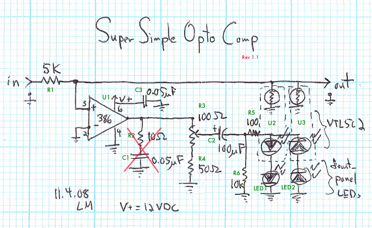
The goal of this variation was to get interesting compression with a bare minimum of parts. There is no makeup gain on board - you'll have to use a mixer channel or something else to bring the signal level back up.
For R3, I was using a 100 ohm linear pot. A reverse log taper might be preferable, as might a value of 200 or 250 ohms - I did not have these parts handy for testing, however.
R4 (placed in series with R3) helps to keep the voltage reaching the Vactrols higher - since the Vactrol and panel indicator LED's in series have a combined voltage drop of roughly 3 volts, it doesn't make sense to "waste" the lowest part of the pot's throw that would just be throttling between 0 and 3 volts. If the value of R3 was raised, and/or changed to a reverse log taper, R4 might not be necessary.
R5 limits the current going to the LEDs. Without it, the loud signals at the heaviest compression settings were getting crackly.
R6 discharges C2 once signal has stopped - otherwise, the LEDs can light up briefly when the threshold pot is lowered.
And, last but not least, I added C3 to cut down on some crazy noise problems. This was not a subtle change! I got lazy with supply bypassing since I just built this on the bench, and I wasn't going to be listening to the output of the 386 anyways. But it makes a huge difference in performance.
Removed - was causing crackling of the output when threshold was in mid-range of its throw: R2 and C1 form the Zobel network recommended by the LM386's datasheet. It is supposed to dampen high frequency oscillation of the '386. I don't have a real oscilloscope here, so I was not able to determine if it's actually necessary in this circuit.
I like the sound of this compressor, especially for having such a low parts count. With the highish voltage drop of the two LEDs in series, however, the onset of its compression action is a bit sudden. I've got something a bit more nuanced planned, expanding upon this idea, but it will double or triple the parts count.
Parts List:
R1 = 5k
R3 = 100 ohm pot
R4 = 50 ohm
R5 = 100 ohm
R6 = 10k
C2 = 100 µF
C3 = 0.05 µF
U1 = LM386
U2, U3 = VTL5C2 vactrols
LED1, LED2 = LEDs for front panel display - or use a single dual-element LED
Thanks again to PRR for all the feedback on this design.
Cheers,
Leigh
EDIT: I slighly modified this today, from what I posted yesterday. Sorry it's looking a bit cramped now.

Circuit Explanation
The goal of this variation was to get interesting compression with a bare minimum of parts. There is no makeup gain on board - you'll have to use a mixer channel or something else to bring the signal level back up.
For R3, I was using a 100 ohm linear pot. A reverse log taper might be preferable, as might a value of 200 or 250 ohms - I did not have these parts handy for testing, however.
R4 (placed in series with R3) helps to keep the voltage reaching the Vactrols higher - since the Vactrol and panel indicator LED's in series have a combined voltage drop of roughly 3 volts, it doesn't make sense to "waste" the lowest part of the pot's throw that would just be throttling between 0 and 3 volts. If the value of R3 was raised, and/or changed to a reverse log taper, R4 might not be necessary.
R5 limits the current going to the LEDs. Without it, the loud signals at the heaviest compression settings were getting crackly.
R6 discharges C2 once signal has stopped - otherwise, the LEDs can light up briefly when the threshold pot is lowered.
And, last but not least, I added C3 to cut down on some crazy noise problems. This was not a subtle change! I got lazy with supply bypassing since I just built this on the bench, and I wasn't going to be listening to the output of the 386 anyways. But it makes a huge difference in performance.
Removed - was causing crackling of the output when threshold was in mid-range of its throw: R2 and C1 form the Zobel network recommended by the LM386's datasheet. It is supposed to dampen high frequency oscillation of the '386. I don't have a real oscilloscope here, so I was not able to determine if it's actually necessary in this circuit.
I like the sound of this compressor, especially for having such a low parts count. With the highish voltage drop of the two LEDs in series, however, the onset of its compression action is a bit sudden. I've got something a bit more nuanced planned, expanding upon this idea, but it will double or triple the parts count.
Parts List:
R1 = 5k
R3 = 100 ohm pot
R4 = 50 ohm
R5 = 100 ohm
R6 = 10k
C2 = 100 µF
C3 = 0.05 µF
U1 = LM386
U2, U3 = VTL5C2 vactrols
LED1, LED2 = LEDs for front panel display - or use a single dual-element LED
Thanks again to PRR for all the feedback on this design.
Cheers,
Leigh


