'T' attenuator response interactions at higher attenuations

GroupDIY Audio Forum

Help Support GroupDIY Audio Forum:

This site may earn a commission from merchant affiliate links, including eBay, Amazon, and others.

emrr

Well-known member
Joined
Apr 12, 2006
Messages
8,649
Location
NC, USA
I notice these high attenuation changes in T attenuator response, and I'd guess most people don't ever look at response plots to know it can be of concern.  These examples are the standard modern 'not quite' a proper 'T' attenuator (because they don't go open and have a minimum loss, rather than 0dB minimum loss) as sold by CAPI, Hairball, and others, and the basic concern is to be noted with all vintage ones as well. 

It's usually not a problem because we don't usually operate in these high attenuation zones, but I will say I see it in this range with vintage limiters like the Gates SA-39 and any others with T's or ladders on the input that run with high attenuation from modern signal levels.  An additional front end pad to change the range can be beneficial. 

This example is a popular transformer coupled preamp with ‘T’ on the output after the transformer, but it's not specific to that particular amp.  The knob runs the typical 7 o'clock to 5 o'clock range.
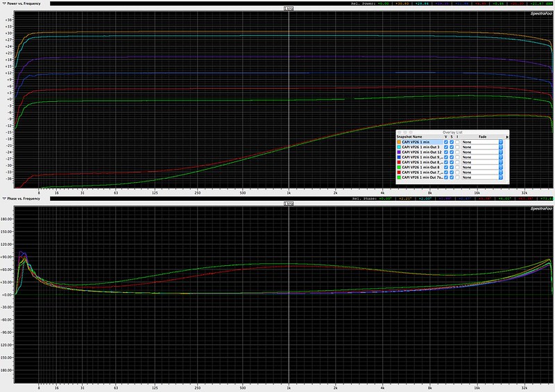
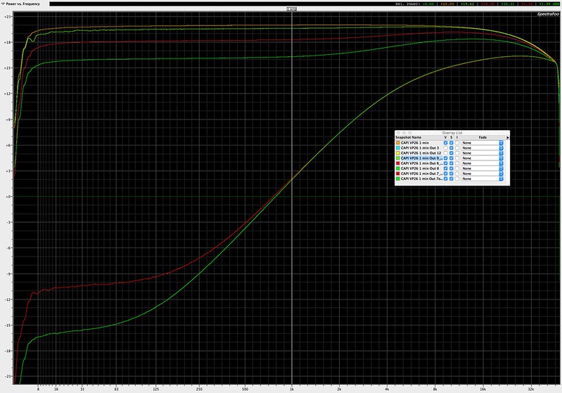
9 o'clock.  0.2dB treble boost.  This is the beginning of frequency deviation.  -19dB @ 1kHz.
8:30 o'clock.  0.8 dB treble boost.  -26dB @ 1kHz.
8 o'clock.  2.3dB treble boost.  -31dB @ 1kHz.
7:30 o'clock.  Middle of phase starts to blow out.  26dB shelf boost difference from 30Hz to 20kHz.
7 o'clock (off).  Middle of phase blows out further.  27dB shelf boost difference from 30Hz to 20kHz.

This may speak a bit to unintended results from people using the output pad rather than the input pad, outside of distortion changes. 

First we have the attenuation amounts separated by gain:
full size pic HERE
45932350604_8f4316a5a3_c.jpg


Then we have gain matched to show the equalization changes:
full size pic HERE
46604624852_a3b4f9d838_c.jpg
 
I saw an article in Jan 1951 Audio Engineering about terminal impedances of attenuators. it's effects...... and some technique to use to determine...etc.... ...  Wonder if it's of any relevance to the topic?
 
Probably....link?  Lots of old articles about attenuators and pads that get into more specifics.
 
EmRR said:
Probably....link? 

https://www.google.com/url?sa=t&rct=j&q=&esrc=s&source=web&cd=1&cad=rja&uact=8&ved=2ahUKEwjXr-_uh9_fAhVO5awKHXFfAAUQFjAAegQIChAC&url=https%3A%2F%2Fwww.americanradiohistory.com%2FArchive-Audio%2F50s%2FAudio-1951-Jan.pdf&usg=AOvVaw0OZoxjTrznVpjeLyaXICh3

part 2

https://www.google.com/url?sa=t&rct=j&q=&esrc=s&source=web&cd=3&cad=rja&uact=8&ved=2ahUKEwjCxKqbiN_fAhUGVa0KHcXnBZMQFjACegQICBAC&url=https%3A%2F%2Fwww.americanradiohistory.com%2FArchive-Audio%2F50s%2FAudio-1951-Feb.pdf&usg=AOvVaw3pENjLMvmT6GAwVsfCU3oq
 
More about determining specific matches, I didn't notice any of the warnings about extremities of operation. 
 
Just wanted to say thanks EMRR,  I was just about to add an attenuator to the tx output of the 1st stage of my group cards, and now I think I'll add a pad there as well.  ;)

Edit: BTW you said 'front end' pad does this mean your pad suggestion is on the input side of amplification, with the t attenuator on the output?  Which is to ask, would adding the pad do any good?
 
boji said:
BTW you said 'front end' pad does this mean your pad suggestion is on the input side of amplification, with the t attenuator on the output?  Which is to ask, would adding the pad do any good?

EmRR said:
I see it in this range with vintage limiters like the Gates SA-39 and any others with T's or ladders on the input that run with high attenuation from modern signal levels.  An additional front end pad to change the range can be beneficial. 
 

All ye olde attenuator tomes address maximum useful attenuation from any single pad, and state that you are better off using two pads in series, any position, input or output.  As in, you need 60 dB, use two 30 dB pads in series.  I've put a switchable 20 dB 'T' pad in front of a variable 'T' on a few limiters, so the variable can range better for varying sources.  Some situations call for a pair of fixed pads.  The particular example I showed on an output stage starts to change response about -20dB, which also likely wouldn't ever be used in that amp, but if you need it, or use that same model attenuator on an input, it's worth looking at the useful response range and deciding if you need an additional fixed pad. 

EmRR said:
This may speak a bit to unintended results from people using the output pad rather than the input pad, outside of distortion changes.
 

There I'm addressing the ignorant unwashed hordes who insist input pads are horrible, and chose to overdrive their inputs and use attenuation on the output side.  Which can occasionally be used to effect, but some appear to treat it as an operational standard.
 
Simple resistive pads should be relatively flat frequency response except for expected interaction with capacitive loading.

My experience is mostly with mic preamp front end pads, and the typical design consideration is to present similar source impedance with pad in or out, to realize similar frequency response, interacting with input termination. 

JR

 
JohnRoberts said:
Simple resistive pads should be relatively flat frequency response except for expected interaction with capacitive loading.

My experience is mostly with mic preamp front end pads, and the typical design consideration is to present similar source impedance with pad in or out, to realize similar frequency response, interacting with input termination. 

Yep. 

The Shure 50dB line to mic level barrel pad product.....I frequently see treble rolloff from the interaction of that much series resistance. 

Many ancient transformer mic inputs have unavoidable response interactions with pads, and it's best to tweak the pad values for the situation rather than trusting the average prescription. 
 
EmRR said:
Yep. 

The Shure 50dB line to mic level barrel pad product.....I frequently see treble rolloff from the interaction of that much series resistance. 
I do not have any specific knowledge about the Shure pad, but pads generally involve a resistive divider. A larger value input resistor (or two), and smaller value resistance in shunt across pad output.  The output impedance of such pads are the parallel impedance of both (all) resistors, so generally quite low. Again good design dictates that pad presents similar termination impedance to the mic (roughly 1.5k-2k ohm) and the pad output presents similar source impedance to the preamp as a typical mic (150-200 ohms).

A 50 dB pad probably won't easily meet those exact criteria but would likely present an even lower source impedance, for less HF roll off than a mic (old school pads can add resistor in series with pad output to raise source impedance to target but in a mic preamp front end this isn't lowest noise option.).
Many ancient transformer mic inputs have unavoidable response interactions with pads, and it's best to tweak the pad values for the situation rather than trusting the average prescription.
Many ancient mic preamps were designed with very specific (ancient) mics in mind, so may not fare very well with generic modern gear, optimized for interchangeability.  BTW ancient expectations about what was good frequency response are much relaxed compared to modern gear.

Of course you probably know this better than I.

JR
 
The Shure line to mic pad appears to be a pair of 47K series resistors and a pair of 150 shunts with center tap to ground, meant to provide 50dB attenuation from a line into a mic input. 
 
EmRR said:
The Shure line to mic pad appears to be a pair of 47K series resistors and a pair of 150 shunts with center tap to ground, meant to provide 50dB attenuation from a line into a mic input.
That output impedance will be less than 300 ohms and balanced. That should not cause much HF loss from normal mic terminations.

JR
 
Resistor pads should be flat to GHz.

Your conditions are not defined. What source and load resistance? How much wire going which way?

The rise could be C shunting the top of the T. Or it could be long wires with some L in series with the leg of the T.

The curves are eye-opening but we can't generalize to other situations or even know when we are in the situation you measured.

At least you measured it! I see far too many people "afraid" to experiment and measure.
 
PRR said:
Resistor pads should be flat to GHz.

For sure.  Does old carbon start to show treble losses in extreme cases?

PRR said:
Your conditions are not defined. What source and load resistance? How much wire going which way?

The rise could be C shunting the top of the T. Or it could be long wires with some L in series with the leg of the T.

This case is a popular transformer coupled (floating) kit preamp with a roughly 300Ω output Z, feeding a 10KΩ input Z balanced ADC through a patchbay with about 25 feet of balanced wire.  'T' output pad after the output transformer.  Pretty much the common widely followed application, but more attenuation than most people would ever use.  The most extreme settings look like a transformer with an open winding connection.

I see similar results with T’s and ladders in many transformer coupled cases, though vintage stepped attenuators get closer to 30dB down before response starts to shift.  Something like the early Gates SA-39 tends to run about -28 to -32 on the input, so there’s some treble peaking set at that range. 

PRR said:
The curves are eye-opening but we can't generalize to other situations or even know when we are in the situation you measured.

At least you measured it! I see far too many people "afraid" to experiment and measure.

Yes, that's the point of the post really, one should always measure and not assume and trust. 
 
Very interesting  thread  ...  just working thru it  :)

Thanks EMrR for the data  and also Scott for those really interesting 1951 audio mags  links.

Regards
 
EmRR said:
it's best to tweak the pad values for the situation rather than trusting the average prescription

I just accept a hair of HF loss in this case. It’s usually pretty negligible imo. But if it’s actually a problematic level then yeah, get the calculator out

Your research rules. Thanks for posting
 
EmRR said:
For sure.  Does old carbon start to show treble losses in extreme cases?
A bad, faulty resistor can do anything. Several years ago when I repaired a broken battery charger for my old neighbor's (RIP) electric mobility scooter, I found a resistor that was wildly out of tolerance, causing the charger failure.

resistors_arent_resistor_fig4.jpg


Here is a more typical resistor plot. Note -3dB half power point around 100 MHz.

This case is a popular transformer coupled (floating) kit preamp with a roughly 300Ω output Z, feeding a 10KΩ input Z balanced ADC through a patchbay with about 25 feet of balanced wire.  API clone with a 'T' output pad after the output transformer.  Pretty much the common widely followed application, but more attenuation than most people would ever use.  The most extreme settings look like a transformer with an open winding connection.

I see similar results with T’s and ladders in many transformer coupled cases, though vintage stepped attenuators get closer to 30dB down before response starts to shift.  Something like the early Gates SA-39 tends to run about -28 to -32 on the input, so there’s some treble peaking set at that range. 

Yes, that's the point of the post really, one should always measure and not assume and trust.
When transformers are involved I am more suspicious of them as the vector causing frequency response aberrations.  It is pretty well known (even by me and I'm not the transformer guy) that transformers perform better driven by low source impedances.

To trust and have high confidence in bench measurements they need to make sense, and/or find a rational explanation. Anyone spending decades making bench tests will have seen weird outlier measurements, and hopefully discovered the reality that caused them (been there done that). 

JR

PS: FWIW I stopped using transformers in recording consoles by the early 80s when bipolar transistors were finally low noise enough to make credible front ends (now we can buy ICs). Constant power terminations haven't made sense IMO for decades (except maybe for long phone lines). But maybe this is just a personal affectation of mine.
 
Almost any time you encounter a T or Ladder attenuator in the real world, it's gonna be attached to a transformer. 

I've seen this on a lot of different systems over a decade of looking at plots, across changes in wiring, converter interfaces, etc.  Modern transformers, vintage transformers. 

In the example above, the transformer is driven by a very low source Z.    The T itself presents a heavier load as attenuation increases. 
 
Hey Doug

None of this is what I remembered with the VP26 (or any of my pre's with the t-pad config) so I just ran some quick sweeps. My results are nothing at all like yours. My frequency response sweeps are essentially identical no matter where the attenuator is set...although I did not check below your lowest of -31dB of attenuation.

This is with the test jig on my bench so the cables are short. In/out are both 32".

I'm using my AP Portable One with it's source Z set to 150Ω. AP input Z is 100k Ω. I can't do pretty colored screen plots so I only jotted down the response at 20kHz. Generator signal was appx -42.58dB. Stepped gain switch was set to 12:00. That results in 0dBu @ 1kHz. Response at 20kHz is -0.31dBu.

Setting t-pad to 19dB of attenuation @ 1kHz yields -19.31dB @ 20kHz. (no change)
Setting t-pad to 26dB of attenuation @ 1kHz yields -26.28dB @ 20kHz. (.03dB change)
Setting t-pad to 31dB of attenuation @ 1kHz yields -31.2dB @ 20kHz. (.11dB of change)

I thought, OK, lets try with the AP set to a 600Ω load. Naturally I had to jack the generator up so -41.12dBu at the input gave me 0dB @ 1kHz. Nearly the same response as before at 20kHz. -0.34dBu.

Setting t-pad to 19dB of attenuation @ 1kHz yields -19.32dB @ 20kHz. (.02dB change)
Setting t-pad to 26dB of attenuation @ 1kHz yields -26.29dB @ 20kHz. (.04dB change)
Setting t-pad to 31dB of attenuation @ 1kHz yields -31.28dB @ 20kHz. (.05dB of change)

Not sure what is up with your test configuration but something looks flawed/skewed.
 
I just added two 8' XLR cables in series to the output of my above test rig and did gain 0.05dB @20kHz from the above. Still nowhere near your results.
 
Back
Top