


High frequency lessons learned
Some of us still want to use valves and are hooked on the API module format, so there is the issue of B+ supply. One good way to approach that is to use a high frequency switching boost converter power supply. These are small, cheap, and if filtered correctly and if the frequencies are high enough, can be made to work well in the 500/GDIY51X environment.
Recently I built the GIX-51X put together by gemini86 in a fairly faithful reproduction of Jacob Erland's Gyraf G9 DIY preamp. Rodney adapted the preamp to use a boost converter B+ supply. It is a great project, a nice preamp, and I recommend it.
I was originally fooled into thinking the B+ supply was very noisy, but I was wrong because the first thing I learned upon building this is, if you test it with an oscilloscope, your oscilloscope will lie to you! The frequencies are so high, and the radiation from the switching supply is so great that you have to do this to your oscilloscope probe or the ground strap becomes a winding that picks up signals greater than the ones you are trying to measure.
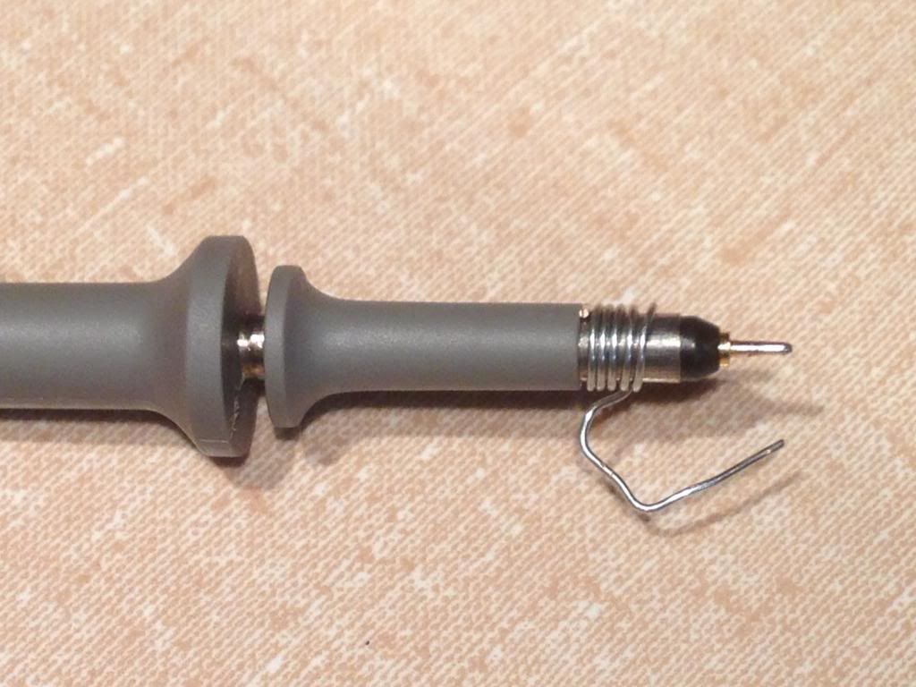
By doing this and wrapping the oscilloscope leads around a ferrite toroid (and for safety make sure you touch the wire to ground before the test point or otherwise ground the scope) you will be able to read better what is going on.
Basic switching
For those unfamiliar, the basic idea of a switching supply is to convert DC to DC either up (boost) or down (buck) by turning an inductor on and off at high frequency, and then rectifying the pulsed current (AC) created by the flux field collapse that happens when an inductor turns off. For a B+ supply the architecture would always have a big discrete MOSFET controlled by the controller to handle the voltage. If this sounds noisy, it is, both from a magnetic field and a ripple current/voltage point of view.
But what Rodney's project showed me is that with filtering and shielding, these noise sources can be managed to levels that are low (below my measurement ability) and in some ways are superior to the linear supplies that we commonly use. This is because the linear supplies we use have much larger magnetics, which produce huge hard to filter fields and to really filter these frequencies the filter circuitry is physically large. Also, the noise is in the audio spectrum (50/60Hz). The switching circuits on the other hand are beyond the audio frequency, they are high frequency and effective shields are thin, and effective filters are physically small.
One problem with switch controllers (plentiful, cheap and powerful) is that the vendors of the "switching controllers" are not thinking so much about vacuum tubes, as they are cell phones and LED lighting supplies! (These generate the highest part sales count). Most DC to DC boost conversion is to take low voltage battery supplied equipment and step it up to a usable level, this allows small batteries with few cells to run powerful things. And of course in that environment size, efficiency an power saving considerations are paramount, and noise is not (MP3 and Cell calls are not high fidelity). And in the LED lighting environment the paramount consideration is efficiency, and the noise filtering is just to keep things within FCC limits (I imagine)!
On the other hand, what we want for a B+ supply is a few milliamps of clean High Voltage and Frequencies that unlikely to have harmonics in the audio range. (Efficiency Ha! We are running heaters!) Ideally we would like high frequency white noise. So when using these controllers, we need to "distort" their original design intent to some extent because instead of Efficiency, Low Voltage and Current we care about Frequency and High Voltage. But it can be done, it is just that most chips are not designed specifically for that purpose.
If you are interested there are some really good resources for learning about this stuff, which I found as I worked on the GIX51X. I attached a great presentation transcript by Alan Martin of Nat Semi on Boost Converter Design Tips, which is really clear and sorts things out. There is a video of this out there somewhere but a PDF slides and transcript of his speech are attached. Good google search terms are "Boost Converter" with or without "Input Filter", "Output Filter" and "EMI".
Rodney has a nice schematic starting place over on the GIX51X thread using the Max1771 although he is looking at alternative chips for future projects.
(I myself looking at "Finger 16" in the GDIY51X rack, and wondering why not put on a B+ Supply (GDIY51XB+). It would easily fit behind the backplane. This would make more space available on the module, and allow good shielding of the supply, or even the use of linear supplies for purists. Maybe safety concerns are too great... )
Some of us still want to use valves and are hooked on the API module format, so there is the issue of B+ supply. One good way to approach that is to use a high frequency switching boost converter power supply. These are small, cheap, and if filtered correctly and if the frequencies are high enough, can be made to work well in the 500/GDIY51X environment.
Recently I built the GIX-51X put together by gemini86 in a fairly faithful reproduction of Jacob Erland's Gyraf G9 DIY preamp. Rodney adapted the preamp to use a boost converter B+ supply. It is a great project, a nice preamp, and I recommend it.
I was originally fooled into thinking the B+ supply was very noisy, but I was wrong because the first thing I learned upon building this is, if you test it with an oscilloscope, your oscilloscope will lie to you! The frequencies are so high, and the radiation from the switching supply is so great that you have to do this to your oscilloscope probe or the ground strap becomes a winding that picks up signals greater than the ones you are trying to measure.
By doing this and wrapping the oscilloscope leads around a ferrite toroid (and for safety make sure you touch the wire to ground before the test point or otherwise ground the scope) you will be able to read better what is going on.
Basic switching
For those unfamiliar, the basic idea of a switching supply is to convert DC to DC either up (boost) or down (buck) by turning an inductor on and off at high frequency, and then rectifying the pulsed current (AC) created by the flux field collapse that happens when an inductor turns off. For a B+ supply the architecture would always have a big discrete MOSFET controlled by the controller to handle the voltage. If this sounds noisy, it is, both from a magnetic field and a ripple current/voltage point of view.
But what Rodney's project showed me is that with filtering and shielding, these noise sources can be managed to levels that are low (below my measurement ability) and in some ways are superior to the linear supplies that we commonly use. This is because the linear supplies we use have much larger magnetics, which produce huge hard to filter fields and to really filter these frequencies the filter circuitry is physically large. Also, the noise is in the audio spectrum (50/60Hz). The switching circuits on the other hand are beyond the audio frequency, they are high frequency and effective shields are thin, and effective filters are physically small.
One problem with switch controllers (plentiful, cheap and powerful) is that the vendors of the "switching controllers" are not thinking so much about vacuum tubes, as they are cell phones and LED lighting supplies! (These generate the highest part sales count). Most DC to DC boost conversion is to take low voltage battery supplied equipment and step it up to a usable level, this allows small batteries with few cells to run powerful things. And of course in that environment size, efficiency an power saving considerations are paramount, and noise is not (MP3 and Cell calls are not high fidelity). And in the LED lighting environment the paramount consideration is efficiency, and the noise filtering is just to keep things within FCC limits (I imagine)!
On the other hand, what we want for a B+ supply is a few milliamps of clean High Voltage and Frequencies that unlikely to have harmonics in the audio range. (Efficiency Ha! We are running heaters!) Ideally we would like high frequency white noise. So when using these controllers, we need to "distort" their original design intent to some extent because instead of Efficiency, Low Voltage and Current we care about Frequency and High Voltage. But it can be done, it is just that most chips are not designed specifically for that purpose.
If you are interested there are some really good resources for learning about this stuff, which I found as I worked on the GIX51X. I attached a great presentation transcript by Alan Martin of Nat Semi on Boost Converter Design Tips, which is really clear and sorts things out. There is a video of this out there somewhere but a PDF slides and transcript of his speech are attached. Good google search terms are "Boost Converter" with or without "Input Filter", "Output Filter" and "EMI".
Rodney has a nice schematic starting place over on the GIX51X thread using the Max1771 although he is looking at alternative chips for future projects.
(I myself looking at "Finger 16" in the GDIY51X rack, and wondering why not put on a B+ Supply (GDIY51XB+). It would easily fit behind the backplane. This would make more space available on the module, and allow good shielding of the supply, or even the use of linear supplies for purists. Maybe safety concerns are too great... )


![Soldering Iron Kit, 120W LED Digital Advanced Solder Iron Soldering Gun kit, 110V Welding Tools, Smart Temperature Control [356℉-932℉], Extra 5pcs Tips, Auto Sleep, Temp Calibration, Orange](https://m.media-amazon.com/images/I/51sFKu9SdeL._SL500_.jpg)

